Translate

Saturday 14 February 2015

Fast Arduino GPS Datalogger.


STOP PRESS! This project is now revised and updated here, and will now create KML files, to open directly in google earth!

Now, my friend Julian and I have, for the past three years, been building a racing car. I've been lending a hand with the electrics and certain mechanical bits.

It's based on a 1971 Mini Clubman (by the name of Florence)

Here's Julian, fitting the door mirror.


After it's first season competing (with Julian at the wheel) , it's not disgraced itself at a few hillclimbs...


This video isn't mine, but this is Julian at the National Championship at Wiscombe Park late last year.

Anyway. Julian wants a bit more power, this has necessitated a new and bigger engine, and a new and bigger carburetor. In turn, the baulkhead had to be modified to accommodate the changes. Now the lovely dashboard we had created to house the instruments had to face some changes, and the large mechanical speedo had to go (when you're racing, you're not looking at how fast you're going!)

We looked for a small speedo that would suit our requirements, but I mooted the idea of a digital speedo, collecting it's data from a GPS receiver... I have previously used U-blox receivers and chipsets commercially, so I ordered one from the lovely people at Hobby Components here.


Excellent. Provides updates at up to 5 times per second.

Now, this coupled to an Arduino pro-mini, and a nice OLED display would provide a nice speedo...

The display is a 128x64 SDD1306 OLED display, and was purchased from eBay.


Then I got to thinking ... what if I could log some data to an SD card as well... might provide some interesting data for when the car is racing. So I ordered an SD card reader at the same time ...


eBay is once again our friend!


Now first things first, we need to configure our GPS receiver. This is done by hooking up the receiver board to our PC (I used the same FTDI converter I use to program the Pro-mini boards).

Go and get yourself a copy of uCenter from the U Blox website here.

Now when the software opens, you will need to tell it which com port and baud rate the receiver is on. Click on the receiver tab, and select the com port. Try 9600 for the baud rate, if you see no data, try another speed. Soon enough you should see some data from the receiver.


Amazing, isn't it!

Now click View and Messages View. Maximise the messages window.

Now scroll down to UBX and click it to expand the tree. Click on CFG . Now click on RATES and change the Measurement Period to 200mS.

Now expand the PORTS section, and change the baudrate to 57600. Once you do this, uCenter will lose communications with the receiver module. Go to Receiver, and re-set the baudrate to 57600.


Now click on Receiver again, selection Action and click Save Config.


You can now disconnect the receiver from the PC.

Now, a word about power. The uBlox receiver is happy at 3.3 or 5v, The Pro-mini I've got is good at 3.3v or 5v, the display works great on 3.3v or 5v... the SD Card reader, whilst it has a pin marked 5v, is only happy with 3.3v on it's data and clock pins. The 5v is purely to power the on-board 3.3v regulator. Now, we can either run everything from 5v and use a level converter between the arduino and the SD card reader (stupid) , or we can use the 3.3v from the card reader's on board reg to drive everything else (a really good idea!)

So, from the car our 12v is dropped to 5v using an ordinary 7805 voltage regulator, this is then supplied to the SD Card reader. The 3.3V pin on the card reader then supplies power to the arduino, the GPS receiver and the display.

SDA on the display is connected to A4, SDC to A5. The SD card interface is connected to pins 4 (CS), 11 (MOSI), 12 (MISO) & 13 (SCK).

A toggle switch is connected between pin 9 and ground. The toggle switch is used to switch on and off the logging feature.

The GPS receiver's TX pin is simply coupled to the hardware RX pin on the arduino, but not until we've uploaded the software!

Now there is an excellent library to control the display from Adafruit, but it is very memory intensive, and somewhat slow. This caused difficulty in writing to the SD card in time.

After spending a while surfing, I happened upon a lightweight library at http://blog.oscarliang.net/arduino-oled-display-library/ which is perfect, although it's not designed for this display. There's a requirement to enable the on-board inverter in our sketch.

We'll also need the most excellent TinyGPSPlus library from https://github.com/mikalhart/TinyGPSPlus

The SD card will need to be formatted on your Windows PC as FAT32. Open notepad and save a blank file as gps.txt to the card.

Here's the schematic:-

You will notice there's a zener diode before the 7805, this to clamp any nasties that might be present on our 12V supply from the vehicle (usually on cranking). Any value between 18 and 32 volts will do. 

 Lashed up for testing...


 7805 power supply.

Will it all fit in the box?


Of course ;)


Painted black to match the dash.

Not many satellites being received on the bench!

But a few in the window!

The receiver is actually very sensitive, although initial lock may take a few minutes, once recent data is stored in the receiver's non-volatile memory, warm starts are very quick indeed.


Out for a quick test run, and logged some data....

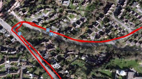
 It's pretty easy to import the txt file into google maps, and get some useful data...


Here, individual data points are shown, each showing the speed at that point.


Anyway, here's the sketch....


/*
Fast GPS data logger.
(c) 14th February 2015 A.G.Doswell

Released to all and sundry under GNU License.

The sketch uses a U-Blox 6M GPS satellite module connected to the hardware serial interface, 
a 128x64 SDD1306 OLED display module connected as an I2C device to pins A4 (SDA)& A5 (SCL) and an SD card interface 
connected to pins 4 (CS), 11 (MOSI), 12 (MISO) & 13 (SCK) The arduino used is a Nano with 3.3v ATMEGA328P.
Warning - Many SD card interfaces are not 5V. 
There's a toggle switch which connects pin 9 to GND for Record.
Data is written to the card an impressive 4 times per second, in real-time. 

The OzOled library is not quite "right" for this application, but works, and is lightweight and fast enough. Thanks Oscar!
It is available here : http://blog.oscarliang.net/arduino-oled-display-library/
TinyGPSPlus is available here :https://github.com/mikalhart/TinyGPSPlus

*/

#include <SPI.h>
#include <Wire.h>
#include <OzOLED.h>
#include <TinyGPS++.h>
#include <SD.h>

static const uint32_t GPSBaud = 57600;
int SatVal;                        // Number of satellites locked
int Speed;                         // Speed in MPH
char SpeedA [4];                   // Speed as char
TinyGPSPlus gps;                   // Feed gps data to TinySGPSPlus
File myFile;                       // Start SD
int speedDigit;                    // Number of digits in Speedo display 
boolean card;                      // Is there a card present?
boolean rec = false;               // Is the record switch low? (false = high)
int recPin = 9;                    // Record pin (Pull low to record data) 

void setup()   {                

  Serial.begin(GPSBaud);           // Start GPS serial comms
  pinMode (recPin, INPUT_PULLUP);  // recPin as input and pulled high
  OzOled.init();                   // initialze SDD1306 OLED display
  OzOled.sendCommand(0x8d);        // Set displays inbuilt inverter on
  OzOled.sendCommand(0x14);          
  OzOled.setBrightness(0xFF);      // ... and brightness to max
  OzOled.clearDisplay();           // Clear the screen
  OzOled.setNormalDisplay();       // Set display to Normal mode
  pinMode(10, OUTPUT);             // CS for SD card, wether it likes it, or not.
  OzOled.clearDisplay();
  
  
  if (!SD.begin(4)) {              //Check SD card is present
      OzOled.printString("SD card fail    ",0,7);
      card = false;  
      }
      else {
      OzOled.printString("SD card OK      ",0,7);
      card = true;
      }
  
  OzOled.printString("Sats:",0,0);  // Set up display
  OzOled.printString("Speed:",0,1);
  OzOled.printString("MPH",7,6);
}

void loop() {
    while (Serial.available() > 0) //While GPS message received
    if (gps.encode(Serial.read()))
      displayInfo();
}

void displayInfo() {               // Display the data
  SatVal = int(gps.satellites.value());
  Speed = int(gps.speed.mph());
  itoa (Speed,SpeedA,10);
  OzOled.printNumber ((long)SatVal,6,0);
  OzOled.printBigNumber (SpeedA, 7,1);
  speedDigit = strlen(SpeedA);    // get length of Speed , and delete left behind zero if req'd
  if (speedDigit == 1) OzOled.printBigNumber(" ",10,1);
  if (digitalRead(recPin) == HIGH && card == true) { //If the record switch is high and the card is OK, write card data
    rec = true;
    OzOled.printString("SD card OK REC",0,7);
  }
  if (digitalRead(recPin) == LOW && card == true) {
    rec = false;
    OzOled.printString("SD card OK    ",0,7);
  }
  
  if (card==true && rec==true) {
    writeInfo(); //write the data to the SD card
  }
  smartDelay(200);

}

// This custom version of delay() ensures that the gps object
// is being "fed".
static void smartDelay(unsigned long ms)
{
  unsigned long start = millis();
  do 
  {
    while (Serial.available())
      gps.encode(Serial.read());
  } while (millis() - start < ms);
}

void writeInfo() { //Write the data to the SD card Date,Time,Lat,Long,Spped (MPH) and number of satellites locked
  
  myFile = SD.open("gps.txt", FILE_WRITE);
  if (myFile) {
    myFile.print(gps.date.month());
    myFile.print(F("/"));
    myFile.print(gps.date.day());
    myFile.print(F("/"));
    myFile.print(gps.date.year());
    myFile.print(F(","));
    if (gps.time.hour() < 10) myFile.print(F("0"));
    myFile.print(gps.time.hour());
    myFile.print(F(":"));
    if (gps.time.minute() < 10) myFile.print(F("0"));
    myFile.print(gps.time.minute());
    myFile.print(F(":"));
    if (gps.time.second() < 10) myFile.print(F("0"));
    myFile.print(gps.time.second());
    myFile.print(F(","));
    myFile.print(gps.location.lat(), 6);
    myFile.print(F(","));
    myFile.print(gps.location.lng(), 6);
    myFile.print(F(","));
    myFile.print(gps.speed.mph(),1);
    myFile.print(F(","));
    myFile.println(gps.satellites.value());
 // close the file:
    myFile.close();
  }
}

Saturday 24 January 2015

Ekco U353 Basket Case repaired!

There's a lovely chap at work called Terry, who likes to restore old radios and record players. He arrived with this old Ecko U353 in bits in a box. "It's got cut wires and labels and has been got at. Would you like it?" Why not ...


 Wires cut. Looks like someone was going to change the mains smoothing capacitor.
 UL84 getter looks bad.
Most of the white lettering from the scale has gone...
... but on the whole the chassis looks reasonable.


The mains smoothing cap is not original, has been disconnected and is dated Feb '65. It has poor ESR....


.. so each of it's 3 sections is given a few hours on the ole' MK87 Dreadnaught capacitor reformer.....


 .... meanwhile the sad looking UL84 is tested on the AVO two-panel valve tester...

A sad 1.5 mA per Volt. Minimum for a new valve is 9 mA per Volt. No good at all....


Thankfully, we have a NOS replacement. Just look at the difference in the gettering (that's the shiny bit at the top). The new valve is on the left. The gettering is bright and has a nice sharp edge. The blacker the gettering is, the better. This new valve reads 15mA per Volt on the AVO!


Stamped on the chassis is a date ... 1st Sept ...19 ?? 1957 perhaps? Seems a bit early for this receiver...


There were many leaking and cracked Hunts capacitors to be changed, along with some suspect TCC electrolytics. The cathode bypass capacitor for the UL84 was short-circuit. That's probably why the valve was worn out.


 Remembering how there was a small decoupling capacitor in the U319 VHF tuner, which caused issues, I removed the cover to this unit (a much easier job that the U319!!!)
But the decoupling caps are Eire types, and all read in very good condition...


So, after leaving the mains smoother on the reformer with all 3 sections in parallel, the leakage had dropped to a very low 50uA!  ESR was good too, so it was re-installed and connected up. So all in all, 1 valve and 9 capacitors, and we're ready to go! Connect to the safety mains isolation transformer, switch on ....


... and after a few minutes warm up time, the DM70 indicator tube lights, and the set performs well...


In common with most mains sets of the period, the metal chassis is connected straight to one side of our AC line (in normal practice, the neutral)... this is referred to as a "live chassis" (even if it is neutral) , which mean the shafts for the controls are also "live". Now, until a set of insulating knobs can be found, this set can only be safely operated though an isolation transformer.


I did locate a nice shiny set of plastic knobs at a dealer locally. Whilst the knobs are plastic, the shiny coating must be metallic, as they conduct very well! These will NOT be safe!


Anyways, here's some good-looking chap to explain the set to you!

Wednesday 14 January 2015

Hello!

I'd like to say a big "Hello" to Nicu from Romania, who's taken the pond pump controller and added a DHT11 to it to make a weather station.

You can read more here:

http://nicuflorica.blogspot.ro/2015/01/ceas-rtc-cu-ds1307-si-date-mediu-cu.html

Sunday 11 January 2015

Sony KV1320 UB MKI restoration.

This has to be the shortest restoration ever. I normally like a bit of a fight from my restorations! A few juicy faults, but not this one! Testament to the quality of late 60's Japanese Engineering.

Now back in the day, set manufacturers had to pay a license fee to Telefunken to use the PAL system, rumoured to be about £30 a set. Sony got around this by decoding the colour signal in a manner which didn't infringe Telefunken's patents. Sony used a modified NTSC decoder, which had an additional delay line, and the colour was repeated from the previously decoded line, reducing the colour resolution, but on such a small screen this isn't noticeable. Any problems with phase could be corrected with the provided hue control, which PAL receivers didn't have, nor need.

Most of these sets died due to being worn out. It is very rare to find one with a decent CRT in, so I wasn't hoping for much, and anyways I paid little money for it, and it's a KV-1320 MKI, a very early one, as several revisions were made.

Being an early model, it has a 3AT2 EHT rectifier valve, and has the CRT heaters permanently connected and warm (not good for CRT longevity!) , regardless of the mains switch position.

This one arrived dead. No tube heaters, nothing.


Opening the mains plug... and the fuse is open circuit!


Replacing that and great pictures!!


 A quick tweak to the frame height and centering


Sit down, and watch telly! A sticker on the chassis show the manufacturing date as June 1969! Fantastic tube which these pictures really don't do justice to.


This sticker is intriguing. Most sets in the UK of this vintage had "live" chassis working, that is one side of the chassis tied to the neutral of the supply, and this has a warning sticker to that effect, but the set doesn't have this! It's a fully isolated design!

Friday 9 January 2015

Workshop video rack.

Whilst I don't get as much time as I'd like to "play tellys", the state of the workshop video sources has been plaguing me recently.

For those outside the UK, I'll explain a little. All TV transmissions in the UK are now digital. They're delivered in Band IV UHF.

In times gone by, there used to be a 405 line black and white only service (System A). This existed  from 1936 until 1984 and started out in Band I VHF, and then expanded into Band III when ITV started in 1955. 625 lines (System I) was introduced for the start of the BBC2 service in 1964, in UHF only (it went colour (PAL) in 1967, and all services moved to UHF 625, both in bands IV and V (Band V has now been flogged off to the mobile phone operators for 4G etc.) )

Now, to run my old tellys we need to generate at least some of these signals. The UHF 625 line colour stuff is easy, just get a DVB receiver (Freeview) with a modulator built in. 405 lines is a little more tricky, but thankfully there exists a small box called an Aurora, which is a 625 line to 405 converter (there are other types available too, to convert between almost anything!)  with a built in VHF modulator. It's superb. Auroras (Auroae?) can be found here. If you are inside the EU, you can order them from Crowthorne tubes here.

The big problem is this motly collection  of boxes and power  supplies, the odd DVD player etc, has just been jury rigged as required. Not a satisfactory situation.

So, I designed myself a little rack to house it all.


 All connections are made on the front panel. This is a workshop piece of equipment, and you don't want to go fiddling around the back. The signal from our aerial (with our digital TV signal on) feeds the top Belling Lee socket, this is passed to a "4G" filter to remove any signals from band V. The RF then feeds the two freeview boxes and the outputs from these (in Band V) are mixed and sent to the mixer in a UHF modulator. The band I output from the Aurora standards converter feeds an attenuator (it's output is hot!) and a low pass filter, this is then combined with the UHF RF and passed (finally!) to the lower Belling Lee locket for connection to the set or sets.


Video to the standards converter is switchable from nothing (which causes the Aurora to output test card C), the Aux input sockets on the front, the DVD or either freeview receivers. Video to the UHF modulator can be switched from the Aux sockets or the DVD player (The freeview is already modulated)


 Much neater and I'm rather pleased with how it's all come out.


I've subsequently added a small Sumvision Cyclone media player to the set up, which is great for playing video files and test cards from a USB memory stick.


Sunday 28 December 2014

Ardunino Astronomical Pond Pump Controller with Frost Protection Update.

Now that we've actually had some cold weather in the UK, I've noticed a couple of minor issues with the controller.

Very occasionally, I've come down on a cold morning to find the controller hung up. I've traced this down to the request loop. When the temp falls too low, the temp sensor can't get the data out in time, and hangs the sketch up. I've slowed the loop down so the temperature is only requested once a minute.

This has also had two beneficial by-products :

1) The time display used to skip a second every now and again whilst the temperature was being requested.
2) The controller does not now repeatedly bounce on and off when the temp is hovering around 1 °C

Sketch follows:
// Dawn & Dusk controller with frost protection.
// 5th December 2014. Modified 28th Dec
// (C) A.G.Doswell 2014
//
// Date and time functions using a DS1307 RTC connected via I2C and Wire lib
//
// Designed to control a relay connected to pin A3. Pin goes low during daylight hours and high during night. Relay uses active low, so is
// "On" during the day. This is connected to the fountain pump in my garden.
//
// Time is set using a rotary encoder with integral push button. The Encoder is connected to interrupt pins D2 & D3 (and GND), 
// and the push button to pin analogue 0 (and GND)
// The RTC is connections are: Analogue pin 4 to SDA. Connect analogue pin 5 to SCL.
// A 2 x 16 LCD display is connected as follows (NOTE. This is NOT conventional, as interrupt pins are required for the encoder)
//  Arduino LCD  
//  D4      DB7
//  D5      DB6
//  D6      DB5
//  D7      DB4
//  D12     RS
//  D13     E
// 
// In this revision, there is a Dallas 18B20 Temperature sensor connected to pin 8, enabling frost protection. This is pulled up to +5volts via a 470K resistor.
//
// Use: Pressing and holding the button will enter the clock set mode (on release of the button). Clock is set using the rotary encoder. 
// The clock must be set to UTC.
// Pressing and releasing the button quickly will display the current sun rise and sun set times. Pressing the button again will enter the mode select menu. 
// Modes are AUTO: On when the sun rises, off when it sets.
//           ON: Permanently ON
//           OFF: Permanently OFF (Who'd have guessed it?)
//
// Change the LATTITUDE and LONGITUDE constant to your location.
// Use the address finder from http://www.hacktronics.com/Tutorials/arduino-1-wire-address-finder.html to find the address of your temperature sensor and enter it where required in DeviceAddress.
// 28th Dec 2014 - Slowed the rate at which the temperature is requested down to once per minute. It has improved the clock display, and solved an issue whereby the temp sensor wasn't always ready to send data, and hung up.
// 
// Be sure to visit my website at http://andydoz.blogspot.com

#include <Wire.h>
#include "RTClib.h" // from https://github.com/adafruit/RTClib
#include <LiquidCrystal.h>
#include <Encoder.h> // from http://www.pjrc.com/teensy/td_libs_Encoder.html
#include <TimeLord.h> // from http://swfltek.com/arduino/timelord.html. When adding it to your IDE, rename the file, removing the "-depreciated" 
#include <OneWire.h> // from http://playground.arduino.cc/Learning/OneWire
#include <DallasTemperature.h> // from http://www.hacktronics.com/code/DallasTemperature.zip. When adding this to your IDE, ensure the .h and .cpp files are in the top directory of the library.


#define ONE_WIRE_BUS 8 // Data wire from temp sensor is plugged into pin 8 on the Arduino
OneWire oneWire(ONE_WIRE_BUS); // Setup a oneWire instance to communicate with any OneWire devices
DeviceAddress outsideThermometer = { 0x28, 0x1A, 0x1A, 0x3E, 0x06, 0x00, 0x00,0xC7 }; // use the address finder from http://www.hacktronics.com/Tutorials/arduino-1-wire-address-finder.html to find the address of your device.
RTC_DS1307 RTC; // Tells the RTC library that we're using a DS1307 RTC
Encoder knob(2, 3); //encoder connected to pins 2 and 3 (and ground)
LiquidCrystal lcd(12, 13, 7, 6, 5, 4); // I used an odd pin combination because I need pin 2 and 3 for the interrupts.
//the variables provide the holding values for the set clock routine
int setyeartemp; 
int setmonthtemp;
int setdaytemp;
int sethourstemp;
int setminstemp;
int setsecs = 0;
int maxday; // maximum number of days in the given month
int TimeMins = 0; // number of seconds since midnight
int TimerMode = 2; //mode 0=Off 1=On 2=Auto
int TimeOut = 10;
int TimeOutCounter;

// These variables are for the push button routine
int buttonstate = 0; //flag to see if the button has been pressed, used internal on the subroutine only
int pushlengthset = 3000; // value for a long push in mS
int pushlength = pushlengthset; // set default pushlength
int pushstart = 0;// sets default push value for the button going low
int pushstop = 0;// sets the default value for when the button goes back high

int knobval; // value for the rotation of the knob
boolean buttonflag = false; // default value for the button flag
float tempC; // Temperature


const int TIMEZONE = 0; //UTC
const float LATITUDE = 51.89, LONGITUDE = -2.04; // set YOUR position here 
int Sunrise, Sunset; //sunrise and sunset expressed as minute of day (0-1439)
TimeLord myLord; // TimeLord Object, Global variable
byte sunTime[]  = {0, 0, 0, 1, 1, 13}; // 17 Oct 2013
int SunriseHour, SunriseMin, SunsetHour, SunsetMin; //Variables used to make a decent display of our sunset and sunrise time.
DallasTemperature sensors(&oneWire); // Pass our oneWire reference to Dallas Temperature.

void setup () {
    //Serial.begin(57600); //start debug serial interface
    Wire.begin(); //start I2C interface
    RTC.begin(); //start RTC interface
    lcd.begin(16,2); //Start LCD (defined as 16 x 2 characters)
    lcd.clear(); 
    pinMode(A0,INPUT);//push button on encoder connected to A0 (and GND)
    digitalWrite(A0,HIGH); //Pull A0 high
    pinMode(A3,OUTPUT); //Relay connected to A3
    digitalWrite (A3, HIGH); //sets relay off (default condition)
    sensors.begin();
    sensors.setResolution(outsideThermometer, 12); // set the resolution to 12 bits (why not?!)
    
    //Checks to see if the RTC is runnning, and if not, sets the time to the time this sketch was compiled.
    if (! RTC.isrunning()) {
    RTC.adjust(DateTime(__DATE__, __TIME__));
  }
 
 
    //Timelord initialisation
    myLord.TimeZone(TIMEZONE * 60);
    myLord.Position(LATITUDE, LONGITUDE);
    CalcSun ();
}
           
void printTemperature(DeviceAddress deviceAddress)
{
  lcd.setCursor (9,1);
  tempC = sensors.getTempC(deviceAddress);
  if (tempC == -127.00) {
    lcd.print("Err");
  } else {
    
    lcd.print(tempC);
    lcd.print((char)0xDF);
    lcd.print("C ");
   
  }
}


void loop () {


    DateTime now = RTC.now(); //get time from RTC
    //Display current time
    lcd.setCursor (0,0);
    lcd.print(now.day(), DEC);
    lcd.print('/');
    lcd.print(now.month());
    lcd.print('/');
    lcd.print(now.year(), DEC);
    lcd.print(" ");
    lcd.setCursor (0,1);
    lcd.print(now.hour(), DEC);
    lcd.print(':');
    if (now.minute() <10) 
      {
        lcd.print("0");
      }
    lcd.print(now.minute(), DEC);
    lcd.print(':');
    if (now.second() <10) 
      {
        lcd.print("0");
      }
    lcd.print(now.second());
    lcd.print(" ");
    
    //current time in minutes since midnight (used to check against sunrise/sunset easily)
    TimeMins = (now.hour() * 60) + now.minute();
   
    
    //Get and display temp every minute
    if (now.second() == 10) {
      sensors.requestTemperatures(); // Request temperature
      printTemperature(outsideThermometer); // display on lcd.
    }
    
    // Calculate sun times once a day at a minute past midnight
    if (TimeMins == 1) {
      CalcSun ();
    }
    if (TimerMode ==2) {
      if (TimeMins >= Sunrise && TimeMins <=Sunset-1 && tempC>=2) { //If it's after sunrise and before sunset, and it's not frozen, switch our relay on
          digitalWrite (A3, LOW);
          lcd.setCursor (13,0);
          lcd.print ("On ");
        }
        else {  //otherwise switch it off
          digitalWrite (A3, HIGH);
          lcd.setCursor (13,0);
          lcd.print ("Off");
        }
      }
       if (TimerMode ==0) {
         digitalWrite (A3, HIGH);
         lcd.setCursor (13,0);
         lcd.print ("Off");
       }
     
       if (TimerMode ==1) {
         digitalWrite (A3, LOW);
         lcd.setCursor (13,0);
         lcd.print ("On ");
       }


    pushlength = pushlengthset;
    pushlength = getpushlength ();
    delay (10);
    
    if (pushlength <pushlengthset) {
      lcd.clear ();
      ShortPush ();   
      lcd.clear ();
    }
    
       
       //This runs the setclock routine if the knob is pushed for a long time
       if (pushlength >pushlengthset) {
         lcd.clear();
         DateTime now = RTC.now();
         setyeartemp=now.year(),DEC;
         setmonthtemp=now.month(),DEC;
         setdaytemp=now.day(),DEC;
         sethourstemp=now.hour(),DEC;
         setminstemp=now.minute(),DEC;
         setclock();
         pushlength = pushlengthset;
       };
}

//sets the clock
void setclock (){
   setyear ();
   lcd.clear ();
   setmonth ();
   lcd.clear ();
   setday ();
   lcd.clear ();
   sethours ();
   lcd.clear ();
   setmins ();
   lcd.clear();
   RTC.adjust(DateTime(setyeartemp,setmonthtemp,setdaytemp,sethourstemp,setminstemp,setsecs)); //set the DS1307 RTC
   CalcSun (); //refresh the sunrise and sunset times
   delay (1000);
   
}

// subroutine to return the length of the button push.
int getpushlength () {
  buttonstate = digitalRead(A0);  
       if(buttonstate == LOW && buttonflag==false) {     
              pushstart = millis();
              buttonflag = true;
          };
          
       if (buttonstate == HIGH && buttonflag==true) {
         pushstop = millis ();
         pushlength = pushstop - pushstart;
         buttonflag = false;
       };
       return pushlength;
}
// The following subroutines set the individual clock parameters
int setyear () {
   lcd.setCursor (0,0);
    lcd.print ("Set Year");
    pushlength = pushlengthset;
    pushlength = getpushlength ();
    if (pushlength != pushlengthset) {
      return setyeartemp;
    }

    lcd.setCursor (0,1);
    knob.write(0);
    delay (50);
    knobval=knob.read();
    if (knobval < -1) { //bit of software de-bounce
      knobval = -1;
    }
    if (knobval > 1) {
      knobval = 1;
    }
    setyeartemp=setyeartemp + knobval;
    if (setyeartemp < 2014) { //Year can't be older than currently, it's not a time machine.
      setyeartemp = 2014;
    }
    lcd.print (setyeartemp);
    lcd.print("  "); 
    setyear();
}
  
int setmonth () {

   lcd.setCursor (0,0);
    lcd.print ("Set Month");
    pushlength = pushlengthset;
    pushlength = getpushlength ();
    if (pushlength != pushlengthset) {
      return setmonthtemp;
    }

    lcd.setCursor (0,1);
    knob.write(0);
    delay (50);
    knobval=knob.read();
    if (knobval < -1) {
      knobval = -1;
    }
    if (knobval > 1) {
      knobval = 1;
    }
    setmonthtemp=setmonthtemp + knobval;
    if (setmonthtemp < 1) {// month must be between 1 and 12
      setmonthtemp = 1;
    }
    if (setmonthtemp > 12) {
      setmonthtemp=12;
    }
    lcd.print (setmonthtemp);
    lcd.print("  "); 
    setmonth();
}

int setday () {
  if (setmonthtemp == 4 || setmonthtemp == 5 || setmonthtemp == 9 || setmonthtemp == 11) { //30 days hath September, April June and November
    maxday = 30;
  }
  else {
  maxday = 31; //... all the others have 31
  }
  if (setmonthtemp ==2 && setyeartemp % 4 ==0) { //... Except February alone, and that has 28 days clear, and 29 in a leap year.
    maxday = 29;
  }
  if (setmonthtemp ==2 && setyeartemp % 4 !=0) {
    maxday = 28;
  }
  
   lcd.setCursor (0,0);
    lcd.print ("Set Day");
    pushlength = pushlengthset;
    pushlength = getpushlength ();
    if (pushlength != pushlengthset) {
      return setdaytemp;
    }

    lcd.setCursor (0,1);
    knob.write(0);
    delay (50);
    knobval=knob.read();
    if (knobval < -1) {
      knobval = -1;
    }
    if (knobval > 1) {
      knobval = 1;
    }
    setdaytemp=setdaytemp+ knobval;
    if (setdaytemp < 1) {
      setdaytemp = 1;
    }
    if (setdaytemp > maxday) {
      setdaytemp = maxday;
    }
    lcd.print (setdaytemp);
    lcd.print("  "); 
    setday();
}

int sethours () {
    lcd.setCursor (0,0);
    lcd.print ("Set Hours");
    pushlength = pushlengthset;
    pushlength = getpushlength ();
    if (pushlength != pushlengthset) {
      return sethourstemp;
    }

    lcd.setCursor (0,1);
    knob.write(0);
    delay (50);
    knobval=knob.read();
    if (knobval < -1) {
      knobval = -1;
    }
    if (knobval > 1) {
      knobval = 1;
    }
    sethourstemp=sethourstemp + knobval;
    if (sethourstemp < 1) {
      sethourstemp = 1;
    }
    if (sethourstemp > 23) {
      sethourstemp=23;
    }
    lcd.print (sethourstemp);
    lcd.print("  "); 
    sethours();
}

int setmins () {

   lcd.setCursor (0,0);
    lcd.print ("Set Mins");
    pushlength = pushlengthset;
    pushlength = getpushlength ();
    if (pushlength != pushlengthset) {
      return setminstemp;
    }

    lcd.setCursor (0,1);
    knob.write(0);
    delay (50);
    knobval=knob.read();
    if (knobval < -1) {
      knobval = -1;
    }
    if (knobval > 1) {
      knobval = 1;
    }
    setminstemp=setminstemp + knobval;
    if (setminstemp < 0) {
      setminstemp = 0;
    }
    if (setminstemp > 59) {
      setminstemp=59;
    }
    lcd.print (setminstemp);
    lcd.print("  "); 
    setmins();
}

int setmode () { //Sets the mode of the timer. Auto, On or Off

    lcd.setCursor (0,0);
    lcd.print ("Set Mode");
    pushlength = pushlengthset;
    pushlength = getpushlength ();
    if (pushlength != pushlengthset) {
      return TimerMode;
    }

    lcd.setCursor (0,1);
    knob.write(0);
    delay (50);
    knobval=knob.read();
    if (knobval < -1) {
      knobval = -1;
    }
    if (knobval > 1) {
      knobval = 1;
    }
    TimerMode=TimerMode + knobval;
    if (TimerMode < 0) {
      TimerMode = 0;
    }
    if (TimerMode > 2) {
      TimerMode=2;
    }
    if (TimerMode == 0) {
    lcd.print("Off");
    lcd.print("  "); 
    }
    if (TimerMode == 1) {
    lcd.print("On");
    lcd.print("  "); 
    }
    if (TimerMode == 2) {
    lcd.print("Auto");
    lcd.print("  "); 
    }
    setmode ();
}

int CalcSun () { //Calculates the Sunrise and Sunset times
    DateTime now = RTC.now();
    sunTime[3] = now.day(); // Give Timelord the current date
    sunTime[4] = now.month();
    sunTime[5] = now.year();
    myLord.SunRise(sunTime); // Computes Sun Rise.
    Sunrise = sunTime[2] * 60 + sunTime[1]; // Sunrise returned in minutes past midnight
    SunriseHour = sunTime[2];
    SunriseMin = sunTime [1];
    sunTime[3] = now.day(); // Uses the Time library to give Timelord the current date
    sunTime[4] = now.month();
    sunTime[5] = now.year();
    myLord.SunSet(sunTime); // Computes Sun Set.
    Sunset = sunTime[2] * 60 + sunTime[1]; // Sunset returned in minutes past midnight
    SunsetHour = sunTime[2];
    SunsetMin = sunTime [1];
}

void ShortPush () {
  //This displays the calculated sunrise and sunset times when the knob is pushed for a short time.
for (long Counter = 0; Counter < 604 ; Counter ++) { //returns to the main loop if it's been run 604 times 
                                                     //(don't ask me why I've set 604,it seemed like a good number)
  lcd.setCursor (0,0);
  lcd.print ("Sunrise ");
  lcd.print (SunriseHour);
  lcd.print (":");
  if (SunriseMin <10) 
     {
     lcd.print("0");
     }
  lcd.print (SunriseMin);
  lcd.setCursor (0,1);
  lcd.print ("Sunset ");
  lcd.print (SunsetHour);
  lcd.print (":"); 
    if (SunsetMin <10) 
     {
     lcd.print("0");
     }
  lcd.print (SunsetMin);        

    
  //If the knob is pushed again, enter the mode set menu
  pushlength = pushlengthset;
  pushlength = getpushlength ();
  if (pushlength != pushlengthset) {
    lcd.clear ();
    TimerMode = setmode ();

  }
  
}


}


Thursday 18 December 2014

Dehumidifer data rate.

Since slowing down the frequency of transmission from the controller in the attic, it has become apparent how many transmissions were being lost, either to the data logging receiver or the remote display. Looking back over historical data, the lost in % of expected transmission is much the same as now, just that there are now fewer!

To try and minimise the loss of transmissions, I spent a little time messing with the location of the transmitter and receivers. I also used my scanner tuned to 433.920 MHz to measure the signal strength. It appears everything is little "on the limit".

To try and improve the link margin, I dropped the data rate to a very pedestrian 75 BPS. This didn't really help much. I've got the link to the data logging PC pretty much 100% now, which is good, but the remote display is a little further away, so it does drop the odd message or two, so I've added a timer into the remote receiver sketch, so if a message falls overdue, "O/D" is written to the top right of the display instead of "On" or "off". At least I then know if the data is current or not.

Here's the sketch:

// Receiver Sketch for Dehumidifier controller project
// Written by A.G.Doswell 23 May 2014, modified 18 Dec 2014
// LCD is a Hitachi HD44780 or compatible, attached thus:
// LCD RS pin to digital pin 12
// LCD Enable pin to digital pin 11
// LCD D4 pin to digital pin 5
// LCD D5 pin to digital pin 4
// LCD D6 pin to digital pin 3
// LCD D7 pin to digital pin 2
// RW to GND
// V0 Held high (this may or may not work with your LCD, usual practice is to connect this to a 10K pot between +5 and GND)
// Receiver connected to pin 9


#include <VirtualWire.h>
#include <VirtualWire_Config.h>
#include <LiquidCrystal.h>

LiquidCrystal lcd(12, 11, 5, 4, 3, 2);

int TX_ID =10;
int Temp;
int Humidity;
int Dew;
boolean Output;
unsigned long timer = 0;
unsigned long timer2;


void setup() {
              lcd.begin (16, 2);
              // Virtualwire setup
              vw_set_tx_pin(10); // Even though it's not used, we'll define it so the default doesn't interfere with the LCD library.
              vw_set_rx_pin(9); // RX pin set to pin 9
              vw_setup(75); //sets virtualwire for a tx rate of 75 bits per second, nice and slow! 
              vw_rx_start();     
              }  
void loop()
{
typedef struct rxRemoteData //Defines the received data, this is the same as the TX struct
{
int    TX_ID; 
int    Temp;   
int    Humidity;
int    Dew;
boolean Output;
};

struct rxRemoteData receivedData;
uint8_t rcvdSize = sizeof(receivedData);
timer2 = millis(); // capture current time
if (timer2 > timer+200000) { //if it's more than 200 seconds since the last time a message was received write O/D to the display (overdue)
  lcd.setCursor (13,0);
       lcd.print ("O/D");
}

if (vw_get_message((uint8_t *)&receivedData, &rcvdSize)) 
{
  if (receivedData.TX_ID == 10)     { //Only if the TX_ID=10 do we process the data.
    lcd.setCursor(13,0);
    lcd.print (" Rx");
    delay (100);
    int TX_ID = receivedData.TX_ID;
    int Temp = receivedData.Temp;
    int Humidity = receivedData.Humidity;
    int Dew = receivedData.Dew;
    boolean Output = receivedData.Output;
    
        
      // writes the received data to the LCD
  lcd.clear ();
  lcd.print("Humidity:");
  lcd.print(Humidity);
  lcd.print("%");
  lcd.setCursor(0, 1);
  lcd.print(Temp);
  lcd.print((char)0xDF);
  lcd.print("C");
  lcd.setCursor(6, 1);
  lcd.print("Dew:");
  lcd.print(Dew);
  lcd.print((char)0xDF);
  lcd.print("C");
  
  if (Output == true) {
      lcd.setCursor (13,0);
      lcd.print (" On");
    
  }
     else {
       lcd.setCursor (13,0);
       lcd.print ("off");

           }
  
      } 
timer = millis(); // reset timer
  }
}

// End of file


**STOP PRESS!!!

Range has continued to be poor. So I revisited the remote receiver hardware. In my haste to get it running there was only the very minor decouling of the PSU on the Arduino pro mini board itself. I've added a 10uF cap to the power supply input to the receiver module and 100uF on the output of the 5V regulator. Range is now MUCH improved. 

Monday 15 December 2014

A sad end ... and a new beginning.

Ladies and gentlemen, please. A moment of silence for the workshop's Weller TCP soldering iron.

Since 1995, it has provided many hours of soldering. Repaired countless electronic circuits. Outlasted two marriages. Been a loyal friend. Last month saw the need for a new tip. But, alas, the old one had seized into the element's housing. After a liberal soaking in Plus-gas (other penetrating oils are available), freezing & heating,  the element failed to recover from the procedure.


Thankfully, a new element was just a day away (Here eBay is not your friend. Elements on eBay were very expensive. I got mine from RS Components)

The iron-y (ouch!) is that you need a soldering iron to fit it. Anyway, I have several irons, but none so good as the venerable Weller!

Here's to the next 19 years of service!!

Saturday 13 December 2014

NAD 310 repair.

This nice little 90's amp found it's way to me with the comment ...

"Just needs a squirt of switch cleaner, one of the volume controls doesn't work"


Sadly not.... and I can see marks on the PCB where someone had been liberally spraying the stuff at the poor innocent volume control!

What happens is the joints break up between the volume pots and the PCB... leading to an intermittent or non-existent connection.

A quick solder up of these joints provides a long lasting repair.... if only it was a quick job. Most amplifiers of this design require a considerable amount of disassembly to get to the joints. Joints to and from the phono connectors on back panels present a similar problem.

Just to show you how long this sort of thing takes, here's a time-lapse video I made (and I wanted an excuse to try some sort of overhead camera thing!). This repair took an hour!


... still better than a "soundbar" or other hideous self contained speaker.