"A mate of mine has a Sony reel to reel that's not working, can you take a look?"
Yeah ... why not.
It's a Sony TC-377, very nice.
A quick test, and it refuses to go into play. A common issue, usually to do with sticky grease on the selector cam, worn or perished belts, or worn or perished idlers. Rewind and fast forward are in rude health, so that rules out a couple of the idlers straight away.
Let's get it apart.
Remove all the knobs from the front panel, they should all just pull off, except the pause lever which unscrews clockwise. Remove the head cover, and unscrew the retaining pins. Now I've smelt a rat, they're lose. They're never lose. There are also five retaining screws on the front panel, or rather there should be. One is significant by it's absence. There's one that's easy to overlook... it's by the heads.
The front panel then lifts away.
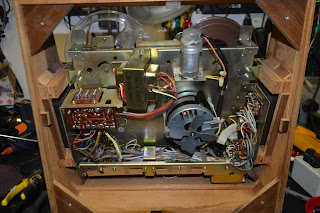
Four screws remove the back panel. We won't need to be in here, but if you have no motor running, or it's just humming and not turning, the chances are that silver motor run capacitor as the top has thrown in the towel, and needs replacement. It's a dual value cap, one is for use on 60Hz supplies, the other, placed in parrallel for 50Hz. You only need to get one value to replace it, unless you intend to go globe-trotting with the thing... For 50Hz operation, you'll need 2.0uF , for 60Hz 1.5uF.
OK, we need to remove the mode selector mechanism, which is a pain. First off remove the three screws circled in red, which will allow you to remove the heads in one piece, don't undo or losen any others!!! There are three brass spacers behind, put them somewhere safe. Now remove the four screws circled in cyan. Note here than one of mine is chewed up ... hmmmm.
You can now extract the mechanism, unhooking the levels and wiggling off the take up belt from the capstan flywheel as you go...
Now, I expect this mechanism to be covered in gold-coloured grease, that is doing the perfect impersonation of glue. Normal procedure is to clean it all of with IPA, diassembling as required, and re-lubricating with superlube or similar.. But this has already been done. Only one issue is the cam select lever has jumped behind it's slot. It's a quick fix...
... but it's not the end of the story. There's a couple of brake pads missing in action, and the capstan drive idler lever is seized up, so the capstan never gets drive. The idler is secured to the lever with a circlip, so that's popped off and removed.
We can't disassemble the lever, as it's riveted together, so some heat is applied to the pivot with the soldering iron, and some penetrating oil gently worked into the pivot. Eventually it starts to move, and some spray grease is eased gently in to prevent re-occurrence. The lever should move freely, and spring back into position.
There are a few other levers on this side of the mechanism which look like they are in need of some attention, so they're sorted out, and new brake pads fabricated and fitted.
Finally the mechanism is reassembled and tested.
The tape has some Christmas carols on, how appropriate.
"Do you remember my Tanberg radio you repaired for me a while back?"
As it happens, I do... I fitted a new telescopic aerial, and cleaned up the controls a bit.
"It's howling, can you look?"
Yeah, why not...
Well, Trevor made a couple of attempts to get it round to me, each time thwarted by the radio, obviously feeling threatened by a trip to see Doz, putting itself right, and behaving again for days.
Eventually the fault was more or less ever-present.
It's a Tandberg Portable 41, dating from around 1970, and just oozes Nordic quality.
I got the thing on the bench , and sure enough it's sat there ... making a sort of mooing noise, that varied in frequency with the volume control.
Let's get the thing in bits...
First off remove the two screws to the left and right of the handle..
Gently bend the handle out and remove it..
Unhook the aluminium side pieces from the bottom of the case, one each side...
You can now remove the wooden "clamshell" from the chassis..
Remove the knobs..
You can now remove the top. You'll notice I removed the telescopic aerial too, there's a screw in the base, and, once removed, it just slides out of the top. I'm not sure it was necessary to do this.
Remove the two handle retaining plates before they fall off..
(It's worth noting how they sit the the grooves in the top panel to aid reassembly later!)
We can now get at the PCB, but access to the component side is difficult...
So remove the speaker , and place it carefully to one side, you won't find another...
Of course, once it was disassembled, the fault vanished....
Some googling occurred, and a schematic obtained.
This website, had a very detailed description of the set, and suggested the "Stabistor" was at fault...
It's a weird looking thing, and, as suggested in the website, is very corroded.. It's shown on the schematic as an ST1,5, given the designator D501, but it's not some sort of diode. It's drawn as a battery, and that's sort of what it is... it's acting as a voltage stabiliser, feeding a stabilised 1.5V supply to the RF & IF stages.
It doesn't look corroded here, as the green corrosion just fell away. It had sort of made it's way down the wire end, and had even corroded the PCB, which took quite a bit of cleaning up before it could be persuaded to take solder again.
"That's bound to be the fault" ... a big bag of red LED's is opened, and each one tested, until I find one with a sensible forward voltage drop, that I can use in place of the stabistor. It's tacked into the circuit, along with a 220uF capacitor to decouple it, and the radio is powered up .... no mooing! Excellent.
I put the radio back together again , and listen to it for the rest of the evening in the workshop.
The following morning , back in the workshop ... and the cow is back ! Damnit.
If the quiescent current adjustment (R518 on the above schematic) is just barely touched, the fault can be *almost* cleared. The instablility is once again permanent.
(As an aside, you may notice the audio output stage is a mix of silicon and germanium transistors)
The audio input to the output stage is disconnected by lifting C506. The fault still persists, so it's in the output stage somewhere....
There's a few electrolytics in there ... C512 (1000uF) is the output coupling capacitor, C513 (1000uF) is some local supply smoothing. These appear to be in reasonable condition, but changing them clears the fault temporarily. It can be made to become unstable again by adjusting the quiescent current again. Voltages on the output pairs base's are unstable... There are only a few electrolytics in the whole set, so they are all swapped out. The fault vanishes once more. The quiescent current control can be rotated and no instability re-occurs .... The quiescent current is reset by measuring the current flowing into the collector of Q503, set for 5mA.
Here's our stabistor replacement LED glowing away. It provides about 1.45V, slightly less than the 1.5V of the original component, but it shouldn't ever fail, and performance doesn't seem affected.
The guilty parties ... and another saved from landfill !
A while back the boss was having a big clear out of this basement, and, having been a fully signed up, Parker-wearing anorak of old, found a GE Superadio 3.
This was made for the US market only, but benefited from a sensitive FM & AM receiver, with an AM "Wide" mode.
In the US, AM channels range from 525KHz to 1705KHz, in 10KHz channels. This gives the station a maximum audio bandwidth of 5KHz, but I suspect many stations may have used more, hence the Superadio being equipped with "Wide" mode for improved audio quality.
In the UK (and EU) , we used 2 AM bands for broadcast , one Longwave (LW or GO in France) and Mediumwave (MW or PO in France). Eventually, after things were standardised throughout Europe, our channels were just 9KHz wide between 525 and 1605KHz (with one other allocation at 1611KHz for Vatican City). This allowed only 4.5KHz of audio, and often a narrower bandwidth of 3.5KHz was used to prevent "splatter" on adjacent channels.
The Superadio is connected up to a variac, and supplied with the required 115V. Nothing. Nada. It's taking no current from the supply. I connect my bench supply, set to 9V to the springs where the 6 D-calls normally reside, and there's a click from the speaker, but nothing more.
Measuring the resistance across the American mains plug shows it's open-circuit. Perhaps the 115V transformer was inadvertently connected to our UK 240V mains, and (rapidly) failed, perhaps damaging the radio circuitry itself before expiring.
Removing the tuning knob, and the bass, treble and volume knobs from the radio, and undoing the 6 screws holding on the back, allow the radio to be removed (not without some struggle) from the case.
The speaker wires are unsoldered, and the workshop speaker temporarily connected.
Getting some life back into the radio is simple, a quick squirt of contact cleaner on the switches and pots restores operation, at least from the bench power supply.
Let's investigate the mains. I'm hoping for a blown fuse, on a transformer which I can simply rewire the primary for 240V operation...
Once the screws to the tuning scale-frame/mechanism and plastic PCB frame are removed, desoldering
the AM radio aerial connector from the rear panel, sufficient access is gained to the underside, where the transformer exists...
It must be under that small fibre cover...
... hang on, what are those three wires that look to have been cut ... some sort of test jig used in production? Surely easier to have used a connector?
The small fibre cover is removed, and all becomes obvious. It's just the strain relief for the mains cable, and a small circuit board for the juction between the transformer primary, and the mains lead (and another mystery component, covered in heatshrink... read on). The transformer is absent without leave. The cover just protected the mains junction, and providing some strain relief for the mains lead. Perhaps the boss removed it to prevent damage if connected up here in the UK?
A small 2 x 6V transformer is ordered, and turns up the next day.
The circuit is very simple. It's just a transformer, and a full-wave rectifier. What bothers me is that mystery component, wrapped in heatshrink. It's connected between one side of the mains, and chassis ground of the radio.
A quick look at the schematic show's it's a 2.2M Ohm resistor. What's it purpose? It would leave the exposed metal battery terminal, as well as the ground terminals on the antenna connector referenced to mains, albeit via a large value resistor.
Am I happy about that? I make a post on the VRAT forum for knowledge.
Whilst awaiting a reply, I remove the american mains lead, as it's not double insulated. And fit a new lead. The original lead, obviously had a american two pin plug on it, and it hides away inside a small compartment in the cabinet when the radio is being used on batteries. Now there's no way a UK plug is going to fit inside that compartment, so I'm going to fit a male IEC connector, on a short bit of lead.
The new transformer is a PCB mounted type, as that's what I could get that would fit. It fits neatly in the hole, and I've superglued it in place, however, it needs some sort of bracket to hold it down.
When I started this repair, I had never used my 3D printer before, so this was first time I've designed something, or 3D printed anything.
A model is created in Fusion 3D. Sliced in Cura, and the results fed into the printer...
And 43 minutes later , it's done!
I have to say, I'm very pleased for a first attempt.
So the conjecture on VRAT is that the 2.2M resistor was probably there to assist signal coupling to ground, and is better and safer left out, as I suspected.
The new transformer has it's two secondary windings connected together, to form a centre tap, and connected up. I've tucked the 2.2M resistor out of the way, so if we ever fancy re-instating it, it's there. I take the opportunity to fit a wire-ended 250mA fuse underneath the junction PCB.
I must say I'm very pleased with the results.
An IEC plug is fitted, so the lead still fits in the rear compartment.
The electronics is tested and it's all working well.
The front speaker grille is removed by bending up the tabs...
... ugh. Years of filth! The speaker is removed...
... and the front case and grille head to the kitchen for a bath.
Once the grille is dry, the GE badge is warmed up with a hot air gun....
and removed ready for a coat of paint....
... duly painted in a fetching shade of satin black..
A break in the handle is repaired..
... and it's primed and painted in the same manner as the grille...
Scratches are polished out of the case with some G3 & elbow grease
... and finally the 3 front panel switches are filled, and the case reassembled...
... and, in doing so I carelessly break the power switch. It's important to make sure the case clears the switch...
Thankfully I didn't lose any of it's parts, and it's quickly crimped back together...
The badge is given a dab of hot glue, and it's refitted to the grille.
The knobs are replaced and the radio tested. It sounds great in 'Wide' AM tuned to Absolute on 1215KHz.
*Further waffle
Then came along "The Pirates" in an attempt to break the BBC's monopoly in the UK. Audio bandwidths were often way wider than the 4.5 KHz permitted, and, certainly channels Like Radio Caroline in the 80's, and the fast-paced Laser 558 produced fabulous (albeit mono) audio. Apparently 9KHz was often the norm, effectively occupying two AM channels. The American Superadio was then a sort-after anorak item for resolving this "extra" bandwidth, despite not being available officially in the UK.
Of course, the last pirate ship fell silent in 1990, but we've got FM (and DAB, I suppose, although quality of DAB can be best described as "variable") now, even if the stations all do sound the same..
Then, after what seemed like an eternity, Radio Caroline managed to get an allocation to permanently transmit on 648KHz. It's got a decent transmitter and aerial (once used by the BBC for the World Service), and can be received further out than it's intended service area of Essex.
Now, as both the boss and myself were interested in it, we set about measuring the bandwidth of Caroline's signal after I commented that it did sound rather "wide". We logged into a few web SDR's to find decent reception, and we measured about 13.8KHz of channel width, corresponding to a very respectable audio bandwidth of 6.9KHz, much outside the required 4.5KHz. Wide indeed. (My boss called people who knew people, who knew people, and ascertained that the audio was indeed 7KHz wide, and the authorities had passed it off, I guess not many people are using AM now, so it's mostly empty, and the problem of adjacent channel splatter has gone away). At the time of writing the BBC is in the process of switching off more medium wave stations up and down the country.