Translate

Showing posts with label RF. Show all posts

Tuesday 28 March 2023

Making an attic antenna for LoRa APRS & TinyGS

Recently I changed my job. 

Sadly this led to the loss of use of the wideband Discone antenna mounted for test purposes on the side of the old building, which I'd used for my TinyGS and LORA APRS igate. 

I have got an iGate at my home, however I'm disappointed by it's woeful performance on the co-linear antenna I fitted in November last year, it requires further investigation when the weather improves!


The plan is to mount a simple quarter wave ground-plane antenna in the attic. 

First things first, an antenna is made up around an SMA connector, and given a tune-up using the Nano VNA. You can get rough dimensions from this great on-line calculator. 

Next, I need to come up with a method to mount the antenna. 

The plan is to mount the antenna on the top of a piece of 20mm electrical conduit, as a simple mast. 


A slotted cylinder and locking ring is 3D printed. It's a bit on the thick side, as the first one I made was a bit thin, and split...


The slotted cylinder fits over the antenna radials, and secures it to the 20mm PVC conduit. As the cylinder is now so thick, it's a really snug fit, and the locking ring is not required. 

The 3D model for the cylinder can be found here :


As I want to feed two receivers (one APRS, one TinyGS) I've fitted an LNA and a splitter (both procured from AliExpress). The LNA will overcome the losses in the splitter (especially as I ordered a 4 output splitter by mistake!). You can just see in this photo, that I coiled the coax around the PVC conduit. This type of thing is usually used as a choke balun. It's not really needed here, but was just a convenient way to tidy up the coax! 

TinyGS
 
LORA APRS


I also connected a third receiver to the output, just as an experiment. This feeds a Raspberry Pi running ionosphere, which as an APRS decoder. This one's tuned to 144.8 MHz, and yes, this antenna isn't going to be much use at that frequency, but let's see how it fares...
Ionosphere can be found at https://github.com/cceremuga/ionosphere
It supports linux, mac os, windows, freebsd, and, of course,  our Raspberry Pi. There's a handy script on the page for installing the software on a pi automatically. 

There's some config to set, but it's quite straightforward.

The Raspberry Pi and SDR are zip tied to the mast...
A supply distribution is made up, consisting of a redundant USB hub & a buck converter. There's a clip-on ferrite between the buck converter and the hub, in an attempt to keep any noise out. This will be fed from a 12v plug in supply once mounted. 


Off to the attic! 
A collegue of mine tells me there's a russian phrase for this kind of construction ... "Проводной с соплями" - "Wired with snot" Yep, it's not tidy!

The Base of the antenna can just been seen, sticking out of a redundant water tank. 


Thankfully, my wifi reaches the attic, and all devices log on to their respective servers...

The two APRS iGates appear on the map ...


and TinyGS is working very well.... This picture was taken after a few days, you can see the increase in the numbers of packets received...
... including some well out of footprint! (Tropospheric ducting, perhaps?) 


Sadly, neither my VHF or UHF APRS stations have captured anything yet, as there's not much traffic here... I'll update you on those as it goes ...


Tuesday 8 November 2022

Aliexpress LoRa Amplifier AB-IOT-433

I've been experimenting with APRS using the T-Beam LoRa hardware, as described in Andreas Spiess HB9BLA Wireless' YouTube video here. (Andreas has two YouTube channels, both are very much worth subscribing to, here and here.)

Now the standard T-beam hardware outputs around 100mW, and I'm getting a range of around 9 miles, although one packet managed to make a 12 mile journey one morning!

Perhaps a little more output power would help.

AliExpress advertises a small RX/TX amplifier. A quick search for "Lora amplifier" pulls up a few, and I bought this one.

It arrives from the seller very promptly. 

It advertises a 2.3W output power at 5V supply, so you will need to have a suitable license to operate this. I have a ham radio license, so I'm good on 433 MHz.

I gave it a quick test on the bench, and it makes 2W happily at 5V, so a real improvement, however the second harmonic is not very well suppressed... 
We're going to need a simple filter. 

Using the tracking oscillator of my Spectrum analyser, I cut an open circuit length of coax to make a suitable stub filter, and once it's cut to the correct length, It's connected via an SMA T connector to the output. 
The output is measured again...


Much improved :) 

I've curled up the stub, which does not effect it's performance, and connected the amp up. It's probably best not to run the amplifier without an antenna or load connected. 
Lashed up in the car for testing... 
And the range now?

Almost no change! I'm not sure what I was expecting. UHF at these frequencies is very line-of-sight, and the range in this case is ultimately defined by terrain. A testament to the robustness of the LoRa protocol at just 100mW, and an interesting, but ultimately pointless experiment! 

Thanks to Jayne, M0JNE, for her help and thoughts on this project.

Monday 8 June 2020

Raspberry Pi Zero NOAA finishing touches.

I'm chuffed with the Pi Zero receiver in the last post, and I'm going to install it in my workshop in Evesham, to take over the job done by the laptop and my FT-817.

I needed to pretty it up a bit.

I found a suitable small case to house the Pi, the SDR and an old LNA (previously failed, but a new amp chip and all is well) 

I got to thinking.... 

Nice if we had some status LEDs on the front panel.

Power (obv.), READY (we've got a pass schedule, so ready to go when a bird pops up), AOS (Acquisition of Satellite) and PROC (processing images).

A front panel is created and printed on a piece of clear acetate, which is then stuck to the front panel with lacquer. It's OK if you don't look too closely...


To drive the LEDs, there are two bash scripts to alter ...

schedule_all.sh and receive_and_process.sh

both are found in ~weather/predict/

schedule_all.sh needs the following lines at the end..

#Switch READY led ON
sudo echo "24" > /sys/class/gpio/export
sudo echo "out" > /sys/class/gpio/gpio24/direction
sudo echo "1" > /sys/class/gpio/gpio24/value

receive_and_process.sh now looks like this..

#!/bin/bash

# $1 = Satellite Name

# $2 = Frequency
# $3 = FileName base
# $4 = TLE File
# $5 = EPOC start time
# $6 = Time to capture

# reads and creates folder with current date / time (i.e 05-30-2019_07-48 *windows friendly*)

NOW=$(date +%m-%d-%Y_%H-%M)
mkdir /home/pi/weather/pics/Folder${NOW}
#switch on AOS led, switch off READY LED
sudo echo "22" > /sys/class/gpio/export
sudo echo "out" > /sys/class/gpio/gpio22/direction
sudo echo "1" > /sys/class/gpio/gpio22/value
sudo echo "0" > /sys/class/gpio/gpio24/value
sudo timeout $6 rtl_fm -f ${2}M -s 60k -g 45 -p 55 -E wav -E deemp -F 9 - | sox -t wav - $3.wav rate 11025
PassStart=`expr $5 + 90`

if [ -e $3.wav ]

then
#switch off AOS led, switch on PROC led
sudo echo "0" > /sys/class/gpio/gpio22/value 
sudo echo "23" > /sys/class/gpio/export
sudo echo "out" > /sys/class/gpio/gpio23/direction
sudo echo "1" > /sys/class/gpio/gpio23/value
/usr/local/bin/wxmap -T "${1}" -H $4 -p 0 -l 0 -o $PassStart ${3}-map.png
/usr/local/bin/wxtoimg -m ${3}-map.png -e ZA $3.wav ${3}.png
/usr/local/bin/wxtoimg -m ${3}-map.png -e CLASS $3.wav ${3}.CLASS.png
/usr/local/bin/wxtoimg -m ${3}-map.png -e MCIR $3.wav ${3}.MCIR.png
/usr/local/bin/wxtoimg -m ${3}-map.png -e MSA $3.wav ${3}.MSA.png
/usr/local/bin/wxtoimg -m ${3}-map.png -e MSA-precip $3.wav ${3}.MSAPRECIP.png
/usr/local/bin/wxtoimg -m ${3}-map.png -e MCIR-PRECIP $3.wav ${3}.MCIRPRECIP.png

fi


# PROC LED off

sudo echo "0" > /sys/class/gpio/gpio23/value

# copies files to the new folder and deletes the original ones

cp /home/pi/weather/*.png /home/pi/weather/pics/Folder${NOW}/
rm /home/pi/weather/pics/Folder${NOW}/*-map.png
rm /home/pi/weather/*.png
rm /home/pi/weather/*.wav
wput -B -u --dont-continue --reupload --tries=5 --binary --verbose --reupload ftp://mywebspaceusername:mypassword@myurl ~/weather/pics/Folder*/*.*
# READY led on
sudo echo "1" > /sys/class/gpio/gpio24/value

You can see from the script that the GPIO pins 22,23 and 24 are used for the LEDs (The POWER LED is driven from the supply). Because only one LED is on at anytime, we can cheat and use only one 220 ohm current limiting resistor to a ground pin, and drive the LEDs directly from the GPIOs, a huge saving of ~3p. Every little helps...

GPIO pin 22 is the AOS LED drive, 23 is PROC, and 24 is READY.

The finished receiver...


In situ, waiting for a pass...


Saturday 6 June 2020

More NOAA APT shenanigans , the £25 NOAA receiver


"Shenanigans" ... that probably doesn't translate well... Wiki says "silly or high-spirited behaviour; mischief."
... anyway ...

There's a bit of talk on the noaa and Raspberry Pi forums, that the new Pi Zero (W) hasn't got enough poke to run a NOAA receiver... so we shall see....

£9.80 is duly shelled out on a Pi Zero W from the lovely people at PiHut.

I thought I'd just clone the existing memory card ... no such luck, the drivers for the Zero's wifi aren't included in Stretch. 

So a new install of Raspberry OS lite is created, and set up. You can follow the instructions here.

You'll need to install wput and lsftp if you want to upload to your webspace.

sudo apt-get wput
sudo apt-get lsftp
You also need to create the pic directory

mkdir ~/weather/pics

Things didn't exactly work out....

That's no good at all...


Now, there are issues with predict on the newer OS. 

When you run predict, and enter your station "callsign", lat, long and height, quitting out leaves the screen in an odd condition, logout, and log back in again.

I had to run predict a number of times before I could get it to swallow all the data... keep running it until it finally shows all fields correctly filled in.

In the previous picture, the receiver had thought it was at 0 degrees long, and 0 degrees lat ... just off the coast of africa! 

After finally getting predict sorted ....  superb pictures are received.

So ... a £14 SDR receiver, and a £9.80 Pi Zero! well, nearly... You'll need a micro SD card and an antenna, but we've saved some money on the computer!

Excellent!

Now my good friend Ben is keen to implement a receiver in Gloucester, and is going this route... once he's up and running, I'll add another page on the NOAA extension to this website, so you can enjoy his pictures as well!


Saturday 11 April 2020

NOAA APT reception on Raspberry Pi


Having been caught by the APT bug again recently (as you may have seen in a previous post) I thought I have a go at building a stand alone system.
I've had some results using my ageing Icom IC-706MKIIB and WXtoIMG on my Ubuntu computer, connected to my ham-radio 2m antenna, but this is less than ideal.
The Evesham receiver uses my employer's wide band Discone antenna, and manages to pull some decent signals in mostly, but doesn't have the required receiver bandwidth, as it's using my FT-817 under CAT control.

OK, Lets start with an antenna....

A QFH antenna would be perfect, but are difficult to make accurately. I found a superb article on a V-dipole antenna here. Some aluminium was duly ordered, and an antenna formed. Tests with the IC-706 gave much improved results. 

The antenna was mounted to a box, using some ordinary chock-block, and also added a low noise RF pre-amp, and bias-tee to power the whole thing from the co-ax (I eventually shortened that piece of co-ax looped round!)


Some pipe clips were fitted so it would be easy to mount.


The box was sealed from the elements with some liquid rubber.


A low current LED was also added to show the presence of bias.


The Receiver

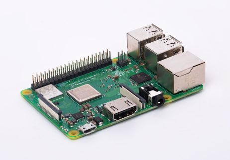
Raspberry Pi 3 Model B+
I loved the idea of a self-contained receiver. It can sit on the shelf, doing it's thing. Some parts were duly procured, a small case, a Raspberry Pi 3 Model B+, an appropriate micro SD card, and a slightly posher SDR tuner with a TXCO (big mistake).


I followed this Instructable to get the basic receiver up and running. It didn't work, so I've updated it...

Grab yourself a fresh install of Raspian stretch lite. I did try a later Raspbian, but Predcit doesn't play nicely with it. Set up SSH, because it helps...

sudo raspi-config

and set up your Pi if you want to change the password, sort out the wifi, I always expand the filesystem too... Allow the Pi to reboot.

then

sudo apt-get update
sudo apt-get upgrade
sudo reboot

So everything's up to date, once we're going again...

sudo apt-get install libusb-1.0 cmake git sox at predict libxft2:armhf

sudo nano /etc/modprobe.d/no-rtl.conf

and add the following to the text file.


blacklist dvb_usb_rtl28xxu
blacklist rtl2832
blacklist rtl2830

CTRL+X to save and quit.

cd ~
git clone https://github.com/keenerd/rtl-sdr.git
cd rtl-sdr/
mkdir build
cd build
cmake ../ -DINSTALL_UDEV_RULES=ON
make
sudo make install
sudo ldconfig
cd ~
sudo cp ./rtl-sdr/rtl-sdr.rules /etc/udev/rules.d/

sudo reboot

wget http://www.wxtoimgrestored.xyz/beta/wxtoimg-armhf-2.11.2-beta.deb
sudo dpkg -i wxtoimg-armhf-2.11.2-beta.deb

Now reboot, and plug in your SDR....

sudo rtl_test

You should see something like the following...

pi@raspberrypi:~ $ rtl_test
Found 1 device(s):
  0:  Generic, RTL2832U, SN: 77771111153705700

Using device 0: Generic RTL2832U
Found Rafael Micro R828D tuner
Supported gain values (29): 0.0 0.9 1.4 2.7 3.7 7.7 8.7 12.5 14.4 15.7 16.6 19.7 20.7 22.9 25.4 28.0 29.7 32.8 33.8 36.4 37.2 38.6 40.2 42.1 43.4 43.9 44.5 48.0 49.6 
Sampling at 2048000 S/s.

Info: This tool will continuously read from the device, and report if
samples get lost. If you observe no further output, everything is fine.

Reading samples in async mode...

Press CTRL+C to get out of that ... 

As the original instructable says, if you get any errors there, you'll need to troubleshoot them...


You can now type

predict

and follow the instructable from part 3, until you get to "Once all three scripts have been created, we need to make the executable, by issuing the following commands:"

You'll need to add sudo ...

sudo chmod +x *.sh

Now you can proceed with crontab-e as described...

OK, except thing's weren't OK.

Every time I recorded I just got static :(

Nothing, nada.

I checked my dongle on my main PC, and it worked great. On the Raspberry Pi, it passed the rtl_test every time.... I was convinced there was something incompatible with the "posh" SDR receiver. This project stopped here, for about a year... then Covid-19 struck, and it's time to resurrect it!

So I bit the bullet and purchased the cheapest RTL dongle I could find....

Bingo...!

I modified the receive_and_process_satellite script to create some prettier pictures, add some friendly folder names, put the received files there, delete the .wav and map files, and chuck the lot onto my web space. I also added samba on to the raspberry pi to make accessing it directly a doddle.

#!/bin/bash

# $1 = Satellite Name
# $2 = Frequency
# $3 = FileName base
# $4 = TLE File
# $5 = EPOC start time
# $6 = Time to capture

# reads and creates folder with current date / time (i.e 05-30-2019_07-48 *windows friendly*)
NOW=$(date +%m-%d-%Y_%H-%M)
mkdir /home/pi/weather/Folder${NOW}

sudo timeout $6 rtl_fm -f ${2}M -s 60k -g 45 -p 55 -E wav -E deemp -F 9 - | sox -t wav - $3.wav rate 11025
PassStart=`expr $5 + 90`
if [ -e $3.wav ]
then
/usr/local/bin/wxmap -T "${1}" -H $4 -p 0 -l 0 -o $PassStart ${3}-map.png
/usr/local/bin/wxtoimg -m ${3}-map.png -e ZA $3.wav ${3}.png
/usr/local/bin/wxtoimg -m ${3}-map.png -e NO $3.wav ${3}.NO.png
/usr/local/bin/wxtoimg -m ${3}-map.png -e MCIR $3.wav ${3}.MCIR.png
/usr/local/bin/wxtoimg -m ${3}-map.png -e MSA $3.wav ${3}.MSA.png
fi

# copies files to the new folder and deletes the original ones
cp /home/pi/weather/*.png /home/pi/weather/Folder${NOW}/
rm /home/pi/weather/Folder${NOW}/*-map.png
rm /home/pi/weather/*.png
rm /home/pi/weather/*.wav
wput -B -u --dont-continue --reupload --tries=5 --binary --verbose --reupload ftp://yourusername:andpassword@yourwebspaceprovider.com/ ~/weather/Folder*/*.*

The Raspberry Pi, Bias T (getting it's 5 volt supply from the raspberry Pi itself), and the SDR receiver are all mounted up in a small case. Sadly I didn't notice the Raspberry Pi had moved to an odd angle before the epoxy set :( ... nevermind. 


The case has an attractive smoked top, which allows me to see the status LEDs. Workshop penny shown for scale.


And finally Mrs Doz states the antenna can live on the corner of the shed.  Mr Pigeon agrees.


.... and quite unbelievably, whilst the antenna was on the ground during assembly....


... it managed to receive this!

Friday 29 July 2016

CCT811 Video modulator massive failure.

Remember my warnings and concern about the CCT811 video modulator?

This is the offending model in question. Apparently it's also being sold under various guises, one model quoted to me is the RF9000. If it looks like this, I'd be seriously concerned....


I wrote about it here. Please take a moment to read this, if you haven't seen it before.

Well, settling down for an afternoon of vintage TV fun, I switched the video rack on....

Crack, crack, crack, bang! Uh-oh...

"It's bound to be the modulator" I thought.


I was right. It had opened the fuse I'd retro-fitted. (If you have one of these awful modulators, time to stop using it!) Damned glad I fitted one... lord knows what would have happened if it had tried to short out the mains without the protection of a fuse... Fire would have been a REAL possibility.

I opened it up and expected to find a mass of blackened bits, but no.  Now I've giving up on this I thought... but it's so useful!

It looks as though the insulation had failed on the transformer, and destroyed the semi-conductors in the drive-side of the supply.

I thought I'd remove the ghastly existing "switched-mode" blocking oscillator, and replace it with something ...

1) Electrically safe.
2) Reliable.

OK. First things first. To find out if it still functions.

I removed the transformer, and connected the workshop power supply between the end of the rectifier diode, and ground....


It seems to want about 6.5 VDC to operate, and has even remembered the settings it had before the power supply failed... good.

It's drawing about 165mA at that voltage, so a supply is not too challenging!


I decided to have a look in the drawer of redundant wall-warts to see if I could find anything suitable, and I spy one of my favourites, an old Nokia phone charger!

Now I always pick these up from boot-sales for a few pence, and are very useful. This one is rated at 3.7 Volts, at 350mA...

"But Andy, you said the modulator needs 6.5 volts to work" ... and so it does, but this particular Nokia charger is unregulated. Off-load it makes about 10 Volts.... Will it make our 6.5 volts at 165mA?

I solder the white +VE lead to the anode of D107, and the black lead to the far right hole (viewed from the rear of the modulator) left behind when I removed the transformer...


... and switch on....

Eureka! It works.


So it's now electrically safe, and I can sit back, and watch some "proper" TV....