Translate

Saturday 30 January 2016

Ferguson 3629 "Personal" Dual-standard monochome television receiver restoration.

It's nearly my birthday, so I thought the wife may turn a blind eye to a "new" TV. There's a sort of "gap" in the collection with regards to 60's dual-standard (405 line/ 625 line) monochrome sets. Then this turned up....


 It's a Ferguson 3629 "Personal" Television, using the Thorn 900 Chassis.


It's a compact set. The 900 chassis is often referred to as the "cool" chassis, designed to use less energy. It features no wasteful "dropper" resistor to obtain the correct voltages, but a mains auto transformer.
 This particular set dates from 1965, and has the early valve UHF Tuner. Later models had a much improved transistor UHF tuner. The VHF Turret tuner can be seen on the right, the UHF tuner on the left. The UHF tuner has the valves enclosed in small screw-on caps.
 Diminutive Mazda CME 1101 CRT

Red EHT rectifier tray. This is semi-conductor, and is mounted on top of the very reliable "jelly-pot" line output transformer.
The system switch can be seen running the whole length of the chassis. This is moved by a switch on the front panel, which moves a flexible cable, which in turn operates the system switch, and a switch on the VHF tuner.


Initial results are encouraging. Very poor frame linearity, and hold. Usually caused by a poor PCL805 or it's cathode decoupling. Not in this case, however! As usual, it was down to a capacitor on the secondary of the frame output transformer. Bob the bodger had previously been at work around the frame stage, and had fitted two replacement resistors (of the wrong value!) and a cap (of the wrong value!) After these were replaced, results on 405 lines were encouraging.


Initial results... poor linearity and frame lock.


UHF 625 operation was not good. Signals are available from my test rack at UHF channel 40, 50 and 60. In addition to signals on 36 and 68 from the house distribution system.

Reception on Ch 36 was OK, if a little grainy. Channel 60 was available strongly, although was extremely touchy to tune, and Channel 68 was good. Where are 40 and 50?

 UHF tuner removed...
 Valves inspected...
 Fine tuning mech cleaned and lubricated. Be very careful not to move any wiring!
 Apparently the small disc ceramic capacitor can crack, it's just to the left of the red coil... it's OK in this tuner.

It turns out that the PC88 is the guilty party!


 Good pictures on 405....

... and 625. After a few minutes some hum starts to disturb the sound and picture.... It's pretty obvious a re-cap of the set will be required...


Quite a few caps are in physically poor condition, or electrically faulty and are replaced, along with the PC88....


The set then functions well, so I re-install the chassis into the cabinet. The set then suffers with intermittent frame collapse (no frame drive), leaving a horizontal line on the centre of the CRT....

After much probing about with an insulated screwdriver, I spot something arcing on the scan coils...

... it's a thermistor (or rather was!). It's turned into a blob of something... I don't have a replacement (and I've got precious little chance of getting one), so I shorted it out, restoring operation.


And here's a video of the set working...

Thursday 21 January 2016

1275GT - the rust continues (to be eliminated!)

Well, back in August the car came home (link here) , and it's been languishing back in the garage awaiting re-charging of funds.

I decided to bite the bullet and get a proper whole front panel. It wasn't cheap, but the front valance was shot. I was going to sped a few hours repairing it, but it had gone round the holes in the front badly, and that was going to be difficult to get right.


 Measurements are made, and spot welds drilled out.... there's some unpleasant bodgery around the headlamp surround. Thankfully the wings are sound.


... and the front comes off,


 The new one is fitted...


... took some cussing, and help from the wife....

... and is finally welded into place.


Now for paint ... (more funds required !!!)

Sunday 17 January 2016

Marantz PM6004 repair

A super chap called Richard from work collared me

"I've got a Marantz amp, intermittent low volume on the left hand channel, usually when changing between speakers A and B , and it only happens on one set of speakers..it's too good to throw out. Can you take a look?"

Yeah ... why not?

 Nice looking modern amp...

 ... and very nicely constructed.
 We're going to have to get the main board out, which is a bit of a struggle as usual, as all the sockets are connected straight to the main board. But before that, let's see if the amp will misbehave for us... Yep, one of the speaker protection relay's doesn't always make it across. They're only rated to 5 amps, which seems a little low for my liking, so some 10 amp relays are obtained, and fitted.


 Here are the guilty parties. Actually only one was faulty, but I changed both to be on the safe side. A check of the bias (it was fine) and a good soak test. An easy fix.


When I returned the amp, the guy said it had always done this since new, and had been returned under warranty twice. Each time it was returned stating "no fault found". I would have thought it was obvious, once the customer's speakers and wiring were eliminated from the equation...

Friday 15 January 2016

Luxman L&G L2800 Amplifier.

This arrived ... "Can you have look mate, been in the attic for years, plugged it in and it hums loudly and gets hot"...

... Yeah, why not.

I initially thought it was some sort of cheapo Japanese "nomark" amp...


Closer inspection reveals it to be made by L&G ... nope, me neither! A google search reveals it's made by Luxman, a well thought of brand in hifi circles, and this is from their L&G "more affordable" range. Apparently designed by Kimura-San of 47Labs & Gain-card fame.


It's of bog-standard 70's Japanese construction. Thankfully you can get to the print side of the board through a hole in the bottom.


A close look at the board shows there's either been some leakage of electrolyte form the caps, or there's been some sort of spillage. It certainly smells like a cat's litter-tray..


More signs of spillage.


This is a bit weird... there are two caps, mounted upside down, despite having more than enough space on the board... Here's one, there's the same on the other side of the board....


Nothing unusual about the output pair, NEC 2SD388A & 2SB541A on the left hand channel ...

nothing unusual that is, unit you look at the right hand channel....


... which is fitted with Toshiba 2SD371 & 2SB531 ! Apparently it's never been repaired before , so it must have left the factory like this! Perhaps they switched supplier and ran out halfway through making this amp!


A few cursory checks, and on with the mains, don't hold out much hope for the caps, but let's find out how bad things are. Left hand channel has a horrible 8V DC offset, and it's all humming very unpleasantly.

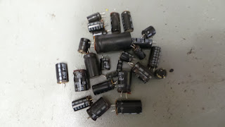
I think we'd better look at those caps. One by one, they are removed, tested and replaced. Some are open, some electrically leaking, many are physically leaking, and none are to tolerance, except the main split-rail smoothing caps, and those two caps mounted upside down!


After a comprehensive re-cap, things are improved, the DC off-set on the left channel is still way too high at 2V. I measure the bias of the right-hand channel at the 0.33 ohm emitter resistors. It's set for 80mA. I set the left the same, and then set the balance up for both channels. DC offset is less than 5mV for both channels.

Now the switch-gear and pots are all noisy, but really nicely made. A good clean up with some switch-cleaner and repeated operation sorts any switching issues and noisy pots are no more.

I soak test the amp for a couple of hours with some fine Yes music, re-checking the bias and offset after an hour, and it's all well. Sounds great, the phono stage is quiet, and it makes a good 50 watts into 8 ohms. Despite different transistors in each channel, I'm damned if I can tell!

The guilty parties ....


Tuesday 5 January 2016

Arduino EEPROM eraser.

I'm working on a small commercial project at the moment, which requires me to store some data into the Arduino's EEPROM. When you upload a new sketch to the Arduino, the EEPROM remains unchanged.

Now a "virgin" arduino has every address in the EEPROM set to 0xFF. Here's a quick sketch to reset the EEPROM to as new, so you can test your code on a fresh arduino.

It outputs to the serial monitor, and blinks Pin 13 on completion.

Apologies for lack of comments, but it's straightforward enough...

 #include <EEPROM.h> //EEPROM interface
 int addr = 0;
 float len;
 int pcComplete;

void setup() {

 Serial.begin (9600);
 Serial.println ("EEPROM Eraser");
 Serial.print("Size of EEPROM =");
 len = EEPROM.length();
 Serial.print (len);
 Serial.println (" bytes");
 delay (1000);
 pinMode(13, OUTPUT);
 }


void loop() {
 EEPROM.write (addr,255);
 Serial.print (addr);
 Serial.print ("  ");
 pcComplete = (addr / len)*100;
 Serial.print (pcComplete);
 Serial.println ("%");
 addr ++;
 if (addr == len+1){
  addr = 0;
  Serial.println ("Complete");
  blinkPin();
  
 }
 }

 void blinkPin () {
  while (1) {
  digitalWrite(13, HIGH);  
  delay(1000);             
  digitalWrite(13, LOW);   
  delay(1000);             
  }
 }