Translate

Showing posts with label Hifi. Show all posts

Monday 20 December 2021

Someone's been here before .... The Sony TC-377.

Jason from the record shop called.

"A mate of mine has a Sony reel to reel that's not working, can you take a look?" 

Yeah ... why not.


It's a Sony TC-377, very nice. 

A quick test, and it refuses to go into play. A common issue, usually to do with sticky grease on the selector cam, worn or perished belts, or worn or perished idlers. Rewind and fast forward are in rude health, so that rules out a couple of the idlers straight away. 

Let's get it apart.

Remove all the knobs from the front panel, they should all just pull off, except the pause lever which unscrews clockwise. Remove the head cover, and unscrew the retaining pins. Now I've smelt a rat, they're lose. They're never lose. There are also five retaining screws on the front panel, or rather there should be. One is significant by it's absence. There's one that's easy to overlook... it's by the heads. 


The front panel then lifts away. 


Four screws remove the back panel. We won't need to be in here, but if you have no motor running, or it's just humming and not turning, the chances are that silver motor run capacitor as the top has thrown in the towel, and needs replacement. It's a dual value cap, one is for use on 60Hz supplies, the other, placed in parrallel for 50Hz. You only need to get one value to replace it, unless you intend to go globe-trotting with the thing... For 50Hz operation, you'll need 2.0uF , for 60Hz 1.5uF. 


OK, we need to remove the mode selector mechanism, which is a pain. First off remove the three screws circled in red, which will allow you to remove the heads in one piece, don't undo or losen any others!!!  There are three brass spacers behind, put them somewhere safe. Now remove the four screws circled in cyan. Note here than one of mine is chewed up ... hmmmm.

You can now extract the mechanism, unhooking the levels and wiggling off the take up belt from the capstan flywheel as you go...  

Now, I expect this mechanism to be covered in gold-coloured grease, that is doing the perfect impersonation of glue. Normal procedure is to clean it all of with IPA, diassembling as required, and re-lubricating with superlube or similar.. But this has already been done. Only one issue is the cam select lever has jumped behind it's slot. It's a quick fix... 
... but it's not the end of the story. There's a couple of brake pads missing in action, and the capstan drive idler lever is seized up, so the capstan never gets drive. The idler is secured to the lever with a circlip, so that's popped off and removed.
We can't disassemble the lever, as it's riveted together, so some heat is applied to the pivot with the soldering iron, and some penetrating oil gently worked into the pivot. Eventually it starts to move, and some spray grease is eased gently in to prevent re-occurrence. The lever should move freely, and spring back into position. 

There are a few other levers on this side of the mechanism which look like they are in need of some attention, so they're sorted out, and new brake pads fabricated and fitted. 

Finally the mechanism is reassembled and tested. 

The tape has some Christmas carols on, how appropriate.


And the case is reassembled. 

Another saved from landfill! 


Sunday 4 July 2021

Aurex (Toshiba) SB-A10B

The ever-cheerful Matin's been badgering me to do a couple of amps for him, a beautiful Luxman R-1040, and an awful Aurex SB-A10B ... he's off on holiday, so dropped them off on his way past...


The label helpfully has the fault description "As they say in Brum, it woo gooo!" which roughly translated means it's doesn't work.

Fancying a quick win before tackling the enjoyable, but somewhat arduous task, of re-capping his Luxman, we'll have a quick look.

It's one of those small form factor separates, and quite well regarded (by those who don't have to fix them) Aurex was Toshiba's "posh" range of hifi.

Something's nagging me in the back of my mind, that last time I did one of these it didn't end well... 


The first challenge is to get the damn thing apart. Remove the Bass, Treble and Volume knobs, and every damn screw you can see... there are plenty. Don't forget the two recessed ones.


Now start wiggling the case around until frustration builds to an almost intolerable level. 


Eventually the top should "ease" forward. Not much room in there....

We need to get the bottom off now....

.. and at this point it's worth noting that the service manual tells lies. At no point does it mention that you need to remove this screw. Remove it. 

Now spend another 5 minutes wiggling the case like a demented fool, only to discover you can't until you remove the two plastic tubes that surrounded those two recessed screws from earlier.


... remove the two plastic tubes, take a deep breath and start wriggling the case like a Tory MP in front of a select committee, until it finally yields. 

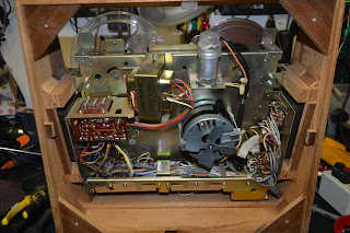
You are now faced with a densely packed lump of electronics. Complete with surface mount resistors (in 1979!) ...


The mains fuse is located under a small plastic cover by the on-off switch. It's visibly blown, and looks to have failed with purpose.

It's a T1A fuse, and is duly replaced.


Voltage is gently increased on the variac, whilst monitoring the current, and it's very clear something is under a lot of load. 

Measuring the output transistors on the left channel, and all is well... measuring the right hand channel and the output transistors (2SB595 and 2SD525 respectively)  are short circuit, well bang goes my quick fix... and they're made from unobtainium (enter the whole of the internet saying they're still available on eBay, off you go and order them then, good luck if they're shot or fakes). Great. 

Some discussions are had with Martin, ruining an otherwise pleasant holiday no doubt, and I reckon an MJE15030 and MJE15031 will do as sunstitues, so some are ordered from a reputable supplier. I will not be beaten by mere machinery. 

I have, however, got an awful sinking feeling... 

... eventually the Luxman is finished (phew!) ... so it's back to this ... 


The heatsink and output transistors are removed as one piece... Both transistors are lose on the heatsink! No small wonder they failed.

The NPN device has been especially warm!

Look at the state of the insulator! We'll have a nice new one.

The MJE15030G and MJE13031G substitutes are pressed into service, after checking the driver transistors are undamaged, which they are...

Both channel's screws are locked into place with a dab of thread lock.

The unit is lashed up naked on the bench, and power is supplied gently via the variac ... after a few seconds the speaker protection relay clicks, indicating there's no DC on the speaker outputs.. Good.


The bias is set up as per the service manual, and speakers connected up... 


... and knock me down with a feather, it all works and sounds great! It's left on test for a while playing The Lasters by Fred Deakin. 

Now the fun and games shoehorning it all back into the case...


... and after much cussing and swearing ... 

... another saved from landfill!

Luxman R-1040 Repairs and restoration.

 Look at it..... 


...Just look at it...

What a thing of beauty. A joy to behold. 


It's a Luxman R-1040 receiver, dating from 1978.
I'm somewhat jealous. A quote from Hifi Engine "It has a genuine output of at least 40 watts continuous per channel into 8 ohms from 20Hz to 20,000Hz with no more than 0.05% total harmonic distortion." That's a very fine spec today, let alone 1978.

This one belongs to cheerful Martin, and has issues. It makes a noise like the tide going out when it's first switched on, some of the lamps have failed, the pots and switches are all scratchy, and Martin would like it re-capped. No mean feat. 

Right, let's crack on... 

There are 6 fittings, which look like they'd be perfectly at home on some Ikea furniture underneath. Remove them with the receiver on it's side, and simple slide the whole chassis out. Put the wooden cover somewhere out of the way, where the cat won't use it as a scratching post.
... it's almost as good looking on the inside as it is on the outside... look at all the space (are you listening Aurex!) 

Access is generally easy. We're going to need to remove the power amp board from the output transistors, and the volume control board to gain access to some of the caps thereon, but it's all very nice.
It appears a cap has let go in the past, as there's some debris... 


A quick look at the service manual and some nice Nichicon caps are on there way. (I would have gone with OE Nippon's, but the price!! I'm damned if I'll pay over £50+VAT each for some of them!) 

You've got to love the march of technology! The new cap on the left, which has a better specification than the old on the right...


The output transistor's heatsink is removed to facilitate change of capacitors, and the output transistors marked up, so they go back in the same order, and the old heatsink grease cleaned off and replaced with thermpath. 


There's a considerable number of caps in this unit, so it takes some number of evenings to complete.


Martin mentioned he wanted the dial lamps replaced, as one had failed... 

This necessitated removal of the front panel...  

.. and the dial glass. 


Despite the remaining dial lamp shining a white light, when it was disassembled, There were two green caps, which had faded / melted with the heat. The original illumination would have been green.


The white wire is disconnected from the power supply tag pin 10, and a 1N4007 diode and a 470uF capacitor are fitted to switch the supply to DC, so we can fit some appropriate LEDs easily...


... nice...


Bias is set for 45mA (after a minute or so's warm up), DC offset nulled out and the pots and switches cleaned.


And finally all buttoned up and tested. 


Monday 31 May 2021

Technics ST-CH7L (CH-7 system). Won't come out of standby.

There I was, minding my own business having a walk at lunchtime along the side of the Avon river, and I bump into a guy I haven't seen for the best part of 15 years. Mark the aerial guy, which is very helpful as I need some aerials fitted on the top of the workshop. Excellent timing.

A couple of weeks later, Mark arrives and sort the new aerials as arranged. He does a superb job as always.

"I've got this Technics hi-fi which won't stay on... could you have a look for me?"

Yeah .... why not?


It's a CH-7 system. Sort of faux-separates where each unit is connected by a ribbon cable to the main amplifier unit. This one refuses to come out of standby. Press the power button, it comes on and instantly off again... 


Eventually it does come on, but the tuner is displaying rubbish... 

A couple more power cycles and it settles down, and works correctly.

You may also notice the display on the amp is all foggy..


The tuner contains all the control circuitry, so I'm going to focus on that first. 

Five screws (two on each side, one on the back) allow the top to be removed. We also need to get the front panel off, held on by two screws underneath.


The screws are removed that secure the PCB to the base... 

The more observant of you will notice the transformer.... surely technics didn't put a mains supply on the ribbon cable? Panic not. This transformer has a 24V primary!


...and the back panel removed to we can remove the main PCB...


R704 looks to have had a hard life. It checks out ok though...


... unlike some of the soldering on the board, which has started to crack up, it's re-worked.

The thing is temporarily reassembled to see if the poor solder is the cause of our issue...

Hopes of a quick and easy fix now fade, it's still the same.


A quick look at the diagram shows there are two main rails, 14.8V , regulated by Q703, and 6.2V , regulated by Q701. 

The 14.8 volts reads good, but not so the 6.2V... it's low at around 4V during the fault condition, but rises up after we have a few goes at getting the thing out of standby.  R701 & 703 check out ok, C704 looks ok on initial inspection, but when removed for testing smells very nasty ! It's job is to stabilise the base voltage on our pass transistor. It's electrically and physically leaky.. C702 measured a little high on ESR, so it's swapped out...

Bingo, the unit is now functioning reliably.

Now to sort out the foggy display on the amp.. 

The top cover is removed, and the front panel in the same manner as the other unit. 


The visible screws are removed from the rear of the front panel PCB. The front panel is made up from two PCB's, we only need to remove the top one.


Pull off the knobs, and remove the 12mm back nuts on both controls.


The pcb is pushed out from the front by pushing on the control shafts. It's got a sort of haze over the vacuum florescent display...


... and the filter in front of it...


... which is easily removed with a spot of window cleaner and a microfibre cloth... 


... and once reassembled, a nice bright display is restored :)


Another saved from landfill !

The guilty parties...