Translate

Showing posts with label Antenna. Show all posts

Tuesday 28 March 2023

Making an attic antenna for LoRa APRS & TinyGS

Recently I changed my job. 

Sadly this led to the loss of use of the wideband Discone antenna mounted for test purposes on the side of the old building, which I'd used for my TinyGS and LORA APRS igate. 

I have got an iGate at my home, however I'm disappointed by it's woeful performance on the co-linear antenna I fitted in November last year, it requires further investigation when the weather improves!


The plan is to mount a simple quarter wave ground-plane antenna in the attic. 

First things first, an antenna is made up around an SMA connector, and given a tune-up using the Nano VNA. You can get rough dimensions from this great on-line calculator. 

Next, I need to come up with a method to mount the antenna. 

The plan is to mount the antenna on the top of a piece of 20mm electrical conduit, as a simple mast. 


A slotted cylinder and locking ring is 3D printed. It's a bit on the thick side, as the first one I made was a bit thin, and split...


The slotted cylinder fits over the antenna radials, and secures it to the 20mm PVC conduit. As the cylinder is now so thick, it's a really snug fit, and the locking ring is not required. 

The 3D model for the cylinder can be found here :


As I want to feed two receivers (one APRS, one TinyGS) I've fitted an LNA and a splitter (both procured from AliExpress). The LNA will overcome the losses in the splitter (especially as I ordered a 4 output splitter by mistake!). You can just see in this photo, that I coiled the coax around the PVC conduit. This type of thing is usually used as a choke balun. It's not really needed here, but was just a convenient way to tidy up the coax! 

TinyGS
 
LORA APRS


I also connected a third receiver to the output, just as an experiment. This feeds a Raspberry Pi running ionosphere, which as an APRS decoder. This one's tuned to 144.8 MHz, and yes, this antenna isn't going to be much use at that frequency, but let's see how it fares...
Ionosphere can be found at https://github.com/cceremuga/ionosphere
It supports linux, mac os, windows, freebsd, and, of course,  our Raspberry Pi. There's a handy script on the page for installing the software on a pi automatically. 

There's some config to set, but it's quite straightforward.

The Raspberry Pi and SDR are zip tied to the mast...
A supply distribution is made up, consisting of a redundant USB hub & a buck converter. There's a clip-on ferrite between the buck converter and the hub, in an attempt to keep any noise out. This will be fed from a 12v plug in supply once mounted. 


Off to the attic! 
A collegue of mine tells me there's a russian phrase for this kind of construction ... "Проводной с соплями" - "Wired with snot" Yep, it's not tidy!

The Base of the antenna can just been seen, sticking out of a redundant water tank. 


Thankfully, my wifi reaches the attic, and all devices log on to their respective servers...

The two APRS iGates appear on the map ...


and TinyGS is working very well.... This picture was taken after a few days, you can see the increase in the numbers of packets received...
... including some well out of footprint! (Tropospheric ducting, perhaps?) 


Sadly, neither my VHF or UHF APRS stations have captured anything yet, as there's not much traffic here... I'll update you on those as it goes ...


Thursday 22 October 2020

BMW Diversity antenna amplifier.

On old school pal, a once estate agent and daytime telly presenter, now a famous comedian (so we'll let him off for the first couple of misdemeanors) dropped me a message on Facebook....

"I've followed some of your repairs with astonishment and very little understanding.

Do you think you could look at something for me?"

Yeah .. why not ..

It's a diversity amplifier from a BMW E61 Tourer. 


They're apparently a really common fault on the E61 tourer, as they're situated in the tailgate, and suffer with water ingress, and Nick confirms this one was full of water when removed, and he'd left it to dry out on a radiator for a few days...

I expect it to be full of corrosion ... 

The plastic case just unclips, and reveals the PCB. 

Which is surprisingly clean and lacking in corrosion... 


So. The plan is to first work out what on earth this thing is supposed to be doing. The faults are the remote locking wasn't working, and the radio would reset to Radio 2 with the bass and treble set to maximum whenever the ignition key was removed... hmmm.

So, a spot of reverse engineering is required. 


The antennas (there are two) seem to feed into the red and black sockets on the top edge of the PCB. I suspect these may well be "hidden" antennas in the glass... The signal is filtered and is sent to a TEA6101 diversity switch. This analyses the signal from each antenna, and sends the strongest one on to the receivers. One signal is sent to a conventional TDA1576 FM demodulator, and on out to an amplifier and off-board via the molded socket. 


The second half goes to a TDA5210 UHF receiver/decoder.. what's the betting that's our remote lock/unlock ? Output from that feeds the IC under the heatsink clamp... 


There's also a small switching supply for +5V, and some amplification and filtering of RF along the way. 

Working out where the +12V power goes to the board, brings up the +5V supply... good. Poking round the data lines with an oscilloscope shows no activity ... but is it expecting data from the car? 

A careful visual inspection of the board under the microscope shows no corrosion. Time to remove the heatsink clamp...

I thought this may be hiding some sort of power amplifier, but no, it's a microcontroller. There's also some corrosion around it's 6MHz ceramic oscillator.... Scoping up around the microcontroller shows no activity ... 


Removing the oscillator shows up the corrosion.. See that black line between the two of those long pads? 


It's duly cleaned up ... 


The oscillator put back into place after checking the bottom of it is clean.... It's soldered back in with the hot air tool.


When I removed the oscillator, I also removed a small decoupling capacitor by accident (there can be some collateral damage with a hot air tool!) ... thankfully I didn't lose it, and this is hand soldered back in place.


I don't think the heatsink clamp is actually anything of the sort. I think it's an RF shield. Anyway it's replaced. Powering up now shows some activity on several of the microcontroller's pins..

 So, it's time to reassemble it, and send it back to Nick to see if it works or not ... fingers crossed.

**** UPDATE **** 
 It worked :)

Saturday 11 April 2020

NOAA APT reception on Raspberry Pi


Having been caught by the APT bug again recently (as you may have seen in a previous post) I thought I have a go at building a stand alone system.
I've had some results using my ageing Icom IC-706MKIIB and WXtoIMG on my Ubuntu computer, connected to my ham-radio 2m antenna, but this is less than ideal.
The Evesham receiver uses my employer's wide band Discone antenna, and manages to pull some decent signals in mostly, but doesn't have the required receiver bandwidth, as it's using my FT-817 under CAT control.

OK, Lets start with an antenna....

A QFH antenna would be perfect, but are difficult to make accurately. I found a superb article on a V-dipole antenna here. Some aluminium was duly ordered, and an antenna formed. Tests with the IC-706 gave much improved results. 

The antenna was mounted to a box, using some ordinary chock-block, and also added a low noise RF pre-amp, and bias-tee to power the whole thing from the co-ax (I eventually shortened that piece of co-ax looped round!)


Some pipe clips were fitted so it would be easy to mount.


The box was sealed from the elements with some liquid rubber.


A low current LED was also added to show the presence of bias.


The Receiver

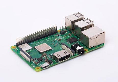
Raspberry Pi 3 Model B+
I loved the idea of a self-contained receiver. It can sit on the shelf, doing it's thing. Some parts were duly procured, a small case, a Raspberry Pi 3 Model B+, an appropriate micro SD card, and a slightly posher SDR tuner with a TXCO (big mistake).


I followed this Instructable to get the basic receiver up and running. It didn't work, so I've updated it...

Grab yourself a fresh install of Raspian stretch lite. I did try a later Raspbian, but Predcit doesn't play nicely with it. Set up SSH, because it helps...

sudo raspi-config

and set up your Pi if you want to change the password, sort out the wifi, I always expand the filesystem too... Allow the Pi to reboot.

then

sudo apt-get update
sudo apt-get upgrade
sudo reboot

So everything's up to date, once we're going again...

sudo apt-get install libusb-1.0 cmake git sox at predict libxft2:armhf

sudo nano /etc/modprobe.d/no-rtl.conf

and add the following to the text file.


blacklist dvb_usb_rtl28xxu
blacklist rtl2832
blacklist rtl2830

CTRL+X to save and quit.

cd ~
git clone https://github.com/keenerd/rtl-sdr.git
cd rtl-sdr/
mkdir build
cd build
cmake ../ -DINSTALL_UDEV_RULES=ON
make
sudo make install
sudo ldconfig
cd ~
sudo cp ./rtl-sdr/rtl-sdr.rules /etc/udev/rules.d/

sudo reboot

wget http://www.wxtoimgrestored.xyz/beta/wxtoimg-armhf-2.11.2-beta.deb
sudo dpkg -i wxtoimg-armhf-2.11.2-beta.deb

Now reboot, and plug in your SDR....

sudo rtl_test

You should see something like the following...

pi@raspberrypi:~ $ rtl_test
Found 1 device(s):
  0:  Generic, RTL2832U, SN: 77771111153705700

Using device 0: Generic RTL2832U
Found Rafael Micro R828D tuner
Supported gain values (29): 0.0 0.9 1.4 2.7 3.7 7.7 8.7 12.5 14.4 15.7 16.6 19.7 20.7 22.9 25.4 28.0 29.7 32.8 33.8 36.4 37.2 38.6 40.2 42.1 43.4 43.9 44.5 48.0 49.6 
Sampling at 2048000 S/s.

Info: This tool will continuously read from the device, and report if
samples get lost. If you observe no further output, everything is fine.

Reading samples in async mode...

Press CTRL+C to get out of that ... 

As the original instructable says, if you get any errors there, you'll need to troubleshoot them...


You can now type

predict

and follow the instructable from part 3, until you get to "Once all three scripts have been created, we need to make the executable, by issuing the following commands:"

You'll need to add sudo ...

sudo chmod +x *.sh

Now you can proceed with crontab-e as described...

OK, except thing's weren't OK.

Every time I recorded I just got static :(

Nothing, nada.

I checked my dongle on my main PC, and it worked great. On the Raspberry Pi, it passed the rtl_test every time.... I was convinced there was something incompatible with the "posh" SDR receiver. This project stopped here, for about a year... then Covid-19 struck, and it's time to resurrect it!

So I bit the bullet and purchased the cheapest RTL dongle I could find....

Bingo...!

I modified the receive_and_process_satellite script to create some prettier pictures, add some friendly folder names, put the received files there, delete the .wav and map files, and chuck the lot onto my web space. I also added samba on to the raspberry pi to make accessing it directly a doddle.

#!/bin/bash

# $1 = Satellite Name
# $2 = Frequency
# $3 = FileName base
# $4 = TLE File
# $5 = EPOC start time
# $6 = Time to capture

# reads and creates folder with current date / time (i.e 05-30-2019_07-48 *windows friendly*)
NOW=$(date +%m-%d-%Y_%H-%M)
mkdir /home/pi/weather/Folder${NOW}

sudo timeout $6 rtl_fm -f ${2}M -s 60k -g 45 -p 55 -E wav -E deemp -F 9 - | sox -t wav - $3.wav rate 11025
PassStart=`expr $5 + 90`
if [ -e $3.wav ]
then
/usr/local/bin/wxmap -T "${1}" -H $4 -p 0 -l 0 -o $PassStart ${3}-map.png
/usr/local/bin/wxtoimg -m ${3}-map.png -e ZA $3.wav ${3}.png
/usr/local/bin/wxtoimg -m ${3}-map.png -e NO $3.wav ${3}.NO.png
/usr/local/bin/wxtoimg -m ${3}-map.png -e MCIR $3.wav ${3}.MCIR.png
/usr/local/bin/wxtoimg -m ${3}-map.png -e MSA $3.wav ${3}.MSA.png
fi

# copies files to the new folder and deletes the original ones
cp /home/pi/weather/*.png /home/pi/weather/Folder${NOW}/
rm /home/pi/weather/Folder${NOW}/*-map.png
rm /home/pi/weather/*.png
rm /home/pi/weather/*.wav
wput -B -u --dont-continue --reupload --tries=5 --binary --verbose --reupload ftp://yourusername:andpassword@yourwebspaceprovider.com/ ~/weather/Folder*/*.*

The Raspberry Pi, Bias T (getting it's 5 volt supply from the raspberry Pi itself), and the SDR receiver are all mounted up in a small case. Sadly I didn't notice the Raspberry Pi had moved to an odd angle before the epoxy set :( ... nevermind. 


The case has an attractive smoked top, which allows me to see the status LEDs. Workshop penny shown for scale.


And finally Mrs Doz states the antenna can live on the corner of the shed.  Mr Pigeon agrees.


.... and quite unbelievably, whilst the antenna was on the ground during assembly....


... it managed to receive this!

Saturday 30 July 2016

The Mirfield Electronics ME-64270 Quad-band 6m, 4m, 2m and 70cm antenna review.

Now I'm not usually one to review things, but this is a bit unusual...

It's a 4 band ham radio antenna. It covers 6m (50 MHz), 4m (70MHz), 2m (145 MHz) and 70cm (430 MHz)

The reason I want to give it some publicity, is the fact that it's small, at only 1.2m in length, covers 4m, and I had some good service from the supplier....

I'd been contemplating sticking something on the roof for a while, to get better access into the local repeaters for a natter on 2m and 70cm every so often. It's got to be fairly small so as not to aggravate the neighbours or the wife....

Then I spotted a small ad in the back of RadCom magazine for a quad-band co-linear antenna. It wasn't too pricey either, having 4m is really good too. Most quad-bands are 10m, 6m,2m and 70cm. I have a magnetic loop that works well on 10m, so that doesn't really interest me.

I placed an order on the website at www.mirfield-electronics.co.uk, and very soon a cardboard tube arrived.

So, it's Sunday. The weather was looking promising, I had half a reel of RG-8 co-ax cable that would do the job, only to be thwarted. One of the radial elements didn't have a thread, and the mounting brackets seemed to be missing... :(

I telephoned the number on Mirfield's website and left a message...

... and a super chap called Martin rang me back about half an hour later (on a Sunday too!). I explained the situation.


He was great, "What WAS I thinking, must have had a bad day!" He promised to post next day, and good to his word, a nice new radial, and the missing mounting brackets turned up on Tuesday.

So, It's Saturday, and once again the weather looks favourable.

I gather the parts and assemble the antenna....


The antenna is fitted with a SO259 "UHF" connector at it's base. Quite why anyone would call it UHF is beyond me. It's a pretty poor connector at VHF, let alone UHF.... anyway, it seemed good enough for Icom to put on the back of their UHF radios, so maybe it's just me... an N-type connector would have been preferable, but at this price point, I'm more than happy.


Having soldered a PL259 on to the RG-8 co-ax, slide the coax and connector through the support tube, making sure the screw hole is pointing towards the antenna. I also slid a piece of heat-shrink tubing on too... Don't do what I did, and forget to slide the mounting clamps onto the mounting tube first!


A couple of laps of self-amalgamating tape are used to give the connector some protection against the elements, and the heat-shrink makes a tidy job ....


... slide the mounting tube onto the bottom of the antenna, and do up the screw. The mounting tube is steel, and I wonder if it could have been made a little thicker for strength. Seems to work OK though...

When doing up the mounting clamps, I found it helpful to keep them flat against the floor, as when you do up the screws, they tend to move about a bit....

I've left the radials off until I get the thing up on the roof...


So, a couple of hours later, and it's up....

(Glad I did it too, the TV co-ax was in an awful state!)


So how's it perform?

Gain figures are quoted as 2.5dBi on 6m, 2.5dBi on 4m, 3.5dBi on 2m, and 5.5dBi on 70cm. I've got no way of checking those, but the antenna opens up repeaters on 2m I haven't heard for years, and fully quietening on local repeaters at just 5 watts. The antenna is rated to 60 watts.

VSWR is better than 1.5:1 on all the frequencies I'm interested in.

Good points...

The service from Mirfield was superb.
It's short.
It's cheap.
It's largely well made, and looks like it will stand the test of time.
70 MHz!

Minor grumbles...

SO259 "good buddy" connector.
Mounting tube could be more robust.