Translate

Showing posts with label Audio. Show all posts

Monday 20 December 2021

Someone's been here before .... The Sony TC-377.

Jason from the record shop called.

"A mate of mine has a Sony reel to reel that's not working, can you take a look?" 

Yeah ... why not.


It's a Sony TC-377, very nice. 

A quick test, and it refuses to go into play. A common issue, usually to do with sticky grease on the selector cam, worn or perished belts, or worn or perished idlers. Rewind and fast forward are in rude health, so that rules out a couple of the idlers straight away. 

Let's get it apart.

Remove all the knobs from the front panel, they should all just pull off, except the pause lever which unscrews clockwise. Remove the head cover, and unscrew the retaining pins. Now I've smelt a rat, they're lose. They're never lose. There are also five retaining screws on the front panel, or rather there should be. One is significant by it's absence. There's one that's easy to overlook... it's by the heads. 


The front panel then lifts away. 


Four screws remove the back panel. We won't need to be in here, but if you have no motor running, or it's just humming and not turning, the chances are that silver motor run capacitor as the top has thrown in the towel, and needs replacement. It's a dual value cap, one is for use on 60Hz supplies, the other, placed in parrallel for 50Hz. You only need to get one value to replace it, unless you intend to go globe-trotting with the thing... For 50Hz operation, you'll need 2.0uF , for 60Hz 1.5uF. 


OK, we need to remove the mode selector mechanism, which is a pain. First off remove the three screws circled in red, which will allow you to remove the heads in one piece, don't undo or losen any others!!!  There are three brass spacers behind, put them somewhere safe. Now remove the four screws circled in cyan. Note here than one of mine is chewed up ... hmmmm.

You can now extract the mechanism, unhooking the levels and wiggling off the take up belt from the capstan flywheel as you go...  

Now, I expect this mechanism to be covered in gold-coloured grease, that is doing the perfect impersonation of glue. Normal procedure is to clean it all of with IPA, diassembling as required, and re-lubricating with superlube or similar.. But this has already been done. Only one issue is the cam select lever has jumped behind it's slot. It's a quick fix... 
... but it's not the end of the story. There's a couple of brake pads missing in action, and the capstan drive idler lever is seized up, so the capstan never gets drive. The idler is secured to the lever with a circlip, so that's popped off and removed.
We can't disassemble the lever, as it's riveted together, so some heat is applied to the pivot with the soldering iron, and some penetrating oil gently worked into the pivot. Eventually it starts to move, and some spray grease is eased gently in to prevent re-occurrence. The lever should move freely, and spring back into position. 

There are a few other levers on this side of the mechanism which look like they are in need of some attention, so they're sorted out, and new brake pads fabricated and fitted. 

Finally the mechanism is reassembled and tested. 

The tape has some Christmas carols on, how appropriate.


And the case is reassembled. 

Another saved from landfill! 


Saturday 4 December 2021

Trevor's Tandberg TP41 and the mystery of the "Stabistor"

 Trevor called..

"Do you remember my Tanberg radio you repaired for me a while back?"

As it happens, I do... I fitted a new telescopic aerial, and cleaned up the controls a bit.

"It's howling, can you look?"

Yeah, why not...

Well, Trevor made a couple of attempts to get it round to me, each time thwarted by the radio, obviously feeling threatened by a trip to see Doz, putting itself right, and behaving again for days.

Eventually the fault was more or less ever-present. 


It's a Tandberg Portable 41, dating from around 1970, and just oozes Nordic quality.


I got the thing on the bench , and sure enough it's sat there ... making a sort of mooing noise, that varied in frequency with the volume control. 

Let's get the thing in bits... 


First off remove the two screws to the left and right of the handle.. 


Gently bend the handle out and remove it..


Unhook the aluminium side pieces from the bottom of the case, one each side... 


You can now remove the wooden "clamshell" from the chassis..

Remove the knobs.. 


You can now remove the top. You'll notice I removed the telescopic aerial too, there's a screw in the base, and, once removed, it just slides out of the top. I'm not sure it was necessary to do this. 


Remove the two handle retaining plates before they fall off.. 


(It's worth noting how they sit the the grooves in the top panel to aid reassembly later!) 


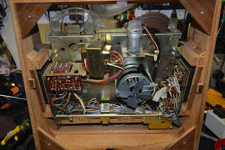
We can now get at the PCB, but access to the component side is difficult... 


So remove the speaker , and place it carefully to one side, you won't find another... 


Of course, once it was disassembled, the fault vanished....

Some googling occurred, and a schematic obtained. 

This website, had a very detailed description of the set, and suggested the "Stabistor" was at fault...


The what? Stabistor?

So, the schematic is consulted.... 


It's a weird looking thing, and, as suggested in the website, is very corroded.. It's shown on the schematic as an ST1,5, given the designator D501, but it's not some sort of diode. It's drawn as a battery, and that's sort of what it is... it's acting as a voltage stabiliser, feeding a stabilised 1.5V supply to the RF & IF stages. 

It doesn't look corroded here, as the green corrosion just fell away. It had sort of made it's way down the wire end, and had even corroded the PCB, which took quite a bit of cleaning up before it could be persuaded to take solder again.


"That's bound to be the fault" ... a big bag of red LED's is opened, and each one tested, until I find one with a sensible forward voltage drop, that I can use in place of the stabistor. It's tacked into the circuit, along with a 220uF capacitor to decouple it, and the radio is powered up .... no mooing! Excellent.

I put the radio back together again , and listen to it for the rest of the evening in the workshop.

The following morning , back in the workshop ... and the cow is back ! Damnit. 

If the quiescent current adjustment (R518 on the above schematic) is just barely touched, the fault can be *almost* cleared. The instablility is once again permanent. 

(As an aside, you may notice the audio output stage is a mix of silicon and germanium transistors) 

The audio input to the output stage is disconnected by lifting C506. The fault still persists, so it's in the output stage somewhere.... 

There's a few electrolytics in there ... C512 (1000uF) is the output coupling capacitor, C513 (1000uF) is some local supply smoothing. These appear to be in reasonable condition, but changing them clears the fault temporarily. It can be made to become unstable again by adjusting the quiescent current again. Voltages on the output pairs base's are unstable... There are only a few electrolytics in the whole set, so they are all swapped out. The fault vanishes once more. The quiescent current control can be rotated and no instability re-occurs .... The quiescent current is reset by measuring the current flowing into the collector of Q503, set for 5mA.

Here's our stabistor replacement LED glowing away. It provides about 1.45V, slightly less than the 1.5V of the original component, but it shouldn't ever fail, and performance doesn't seem affected.


The guilty parties ... and another saved from landfill !


Saturday 28 August 2021

Luxman L-80V repairs and renovations.

The ever-cheerful Martin called ...

"I'm chuffed with the R-1040 you did, can you do my other one?"

Yeah ... why not. 

.. and he brings me another R-1040 to do, and also a rather nice L-80V (which was unexpected, as somewhere our wires had got crossed!)


Luxman do make some nice looking kit.
Martin wants the amp serviced and re-capped. It's got a low-level hum to it.

Anyway , off with the wooden sleeve (in the same manner as the R-1040) and I'm greeted with a very familiar sight...

... it's the same as the L&G L2800 I did here all those years ago, or at least the main PCB is. 

It's also suffering with the same leakage... Let's get re-capping the thing. 


Almost as much of a slog as the R1040....

Most of the electrolytic capacitors are in a woeful state...

Much in the same way as the L&G 2800, output transistors are a mix of manufacturers, this time on the same channels!


To get at the capacitors on the tone control and loudness control boards, first remove the knobs.. 
Then remove the screws securing the front panel, both the aluminium and plastic sections. Theses are
located on the top and bottom of the front panel. 


With the front panel removed...

... undo the securing nuts holding the two tone control pots to the front panel. 


... and, whilst access is still limited, you can now get at the caps on the tone control board


Similar process with the loudness board. Remove the four securing screws... 


... and re-cap the board.

The main smoothing caps, whilst looking in good condition, are both reading low in value. This is probably the cause of the hum. Sadly the caps I used in Martin's R-1040 are now on a long back-order time. Some other Nichicon caps are in stock, so these are ordered, but are of smaller diameter than the originals, so some sleeves are 3D printed, and the caps replaced. I've printed four, because I'm going to need 4 for Martin's other R-1040

Snug...

With the re-cap complete, the bias is set, and the amplifier is a stunning performer. 

It's given a good soak test with the most excellent International Teachers of Pop 


Now to do Martin's other R-1040 !

Wednesday 11 August 2021

Sanyo TP1100 Turntable repair.

Colin rang...

"Got this Sanyo turntable here ... doesn't work, got a new Rega Carbon cartridge on it, but doesn't spin. Nice thing, heavy , all die-cast ... are you interested for £15?" 

Now, under normal circumstances, I would have taken Colin's arm off... but right at the moment, I'm planning a major workshop build, and if I bring anything else into the house, the current Mrs Doz is likely to serve divorce papers. I politely declined.

... time passed ...

Colin rang..

"Need a turntable for Fiona, sensible price.. have you got anything?"

"I haven't, but what about that Sanyo?"

"It doesn't work."

"No, but I'll see to that... "

So it arrives in top-secret, under the cover of darkness....


The turntable powers up OK, and moving the arm over should automatically start the platter. Nope, but the neon stroboscope lights up.... "The lights are on, but there's nobody home".

First off, remove the mat and platter, and place safely out of the way, then remove the screws from the edge of the blow-moulded bottom cover.

There's a DC controlled direct-drive servo motor, and some levers to automate the turntable. 

The simple DC controller is mounted to the impressive die-cast chassis, and is powered from a small transformer, well away from the arm end of the deck.
The turntable's power is controlled by two microswitches attached to a spring loaded lever at the base of the arm. 

The microswitch nearest us controls the power to the neon... The other switches the secondary from the transformer (about 20VAC) to the speed controller board. 


The neon works, but the motor doesn't, and a few checks prove the microswitch isn't working anymore. 

It's removed, and a replacement sourced. 

Unfortunately, the replacement is useless... It requires too much force to engage the switch. The spring on the lever is too weak, and with good reason, its triggered by a cam on the base of the arm... too much force here would be disastrous. 


OK, now a switch with low force is available, but not in that form-factor. Some head scratching ensues... The original (but broken) switch is refitted. The two yellow wires from the broken switch are shorted together, and tidied up. 


The transformer's feed from the LIVE side is disconnected and is now connected to the switched live side of the neon strobe... so when the neon's on, the transformer is connected, and it's output fed to the speed controller... 


... all is well. Almost. 

There's a *click* on the audio as the turntable starts up and stops. We'll have to live with that, until a suitable switch is obtained, anyway ...

Another saved from landfill! 

The turntable is tested with Nicky Thomas "Love of the common people"

Monday 31 May 2021

Leak Stereo 20 Repairs and restoration.

Next up, Ian's Stereo 20

It's a slightly later "chocolate" coloured version (earlier ones where gold) and develops 20 watts from a pair of EL84's (6BQ5) driven from an all ECC-83 (12AX7) layout of preamp and phase-splitters. Power is provided from a GZ32 rectifier.


Dating from 1962, it's nicely laid out, and easy to work on. Looks like it's had some repairs in it's life, especially to the left hand channel (top in this picture) ...


Every capacitor is changed out for new, even though the two cathode bypass capacitors in the pre-amp had been changed some time in '97 accroding to the date codes. The main coupling capacitors were dated 1979. 

A good number of resistors were outside of tolerance, or not to the schematic, and were replaced. If something was out on the left channel (of which there were many), the corresponding part was replaced on the right, so as to avoid upsetting the balance between channels. 

The main cans are re-stuffed with modern 32uF components, and are mounted back using a 3D printed plastic cap.


Whilst the actual foil and (dried out) electrolytic matting were very easy to remove, not so the black sealing goo, which I presume is some kind of bitumen. Leaving the empty cans in the freezer for a few hours (whilst Mrs. Doz was absent!) hardened it, and it was easy to chip off. 


The modern components were a tight fit.


Finished of with a new Cap-cap TM ;)

You can get the files from https://www.thingiverse.com/thing:4872632
Once everything is done, the unit is powered up, and gives reasonable results, albeit down on power. HT is good, but one side has mismatched valves, and the other side, well, they are just tired. Ian told me that he'd borrowed a valve out of his other amp, as one had gone to air. It really does deserve a new set of output valves. 

The guilty parties...