Translate

Showing posts with label Repair. Show all posts

Wednesday 27 July 2022

Mending the Micros - The VIC-20

To create some more interesting content, and explore an avenue of electronics repair I miss, I've been on eBay, and spent some money on some 80's micro-computers. Not just any 80's micro's... oh no, broken ones. 

I was hooked on computers when I was a teen. Ever since my Dad borrowed a Sinclair ZX80 from a colleague of his and I sat there ... typing away on it's membrane keyboard, learning Basic as I went. A couple of years later, one Christmas, the family got an Oric-1 (the 48K model) with colour and sound! As software was somewhat limited, a Sinclair Spectrum followed, and then the mighty Commodore 64. The hours I spent writing stuff in both Basic and assembler... 

If you don't subscribe to me on youTube, you'll have missed the first part of "Mending the micros", where I fix a down-at-heal ZX81, and give it a little more memory. It's here .. https://youtu.be/RDEty5WAtZs

In the spirit of utterly giving myself far too much to do, the Vic-20 is going to be available here, written in my own inimitable style, and in glorious high-definition on youTube here https://youtu.be/u37iBSqEdU8
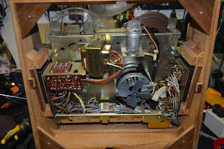
The machine comes in it's original box, with a manual, a power supply, and the "earlier" type of
datasette, the C2N.

It's an early machine, that uses a two-pin plug to supply 9VAC from the small external transformer. If you have a VIC-20 or a C64 with the later type of DIN plug supply, it's important to verify it's operation, or better still, replace it, as they supply both 9VAC, and 5VDC, and the 5VDC commonly rises above maximum limits, and does damage to the machine. 

The machine is disassembled, and given a cursory check over. It looks good, except for the heatsink
which is bolted to the bridge rectifier has worked lose. It's removed, and given some new heatsink compound before refitting the heatsink and securing the screw with a dab of thread lock.

The modulator is connected to the 5-pin output socket, the machine switched on and the trusty workshop TV tuned in... 

OK, a screen full of jumbled characters. Each of the socketed IC's is removed, pins checked and re-seated. No change, unsurprisingly! 


The reset line and 6502 clocks are checked... all fine.

At this point, I decided that booting the VIC-20 dead-test cartridge would be a good idea... except for I don't have one! Thankfully, there is a great open-source project called the VIC-20 Hyper-expander, and it can be found at Sven's site here : http://tech.guitarsite.de/vic-20_hyper_expander.html 

The firmware set one, has dead-test in it. Excellent. A single PCB is ordered from EBay...


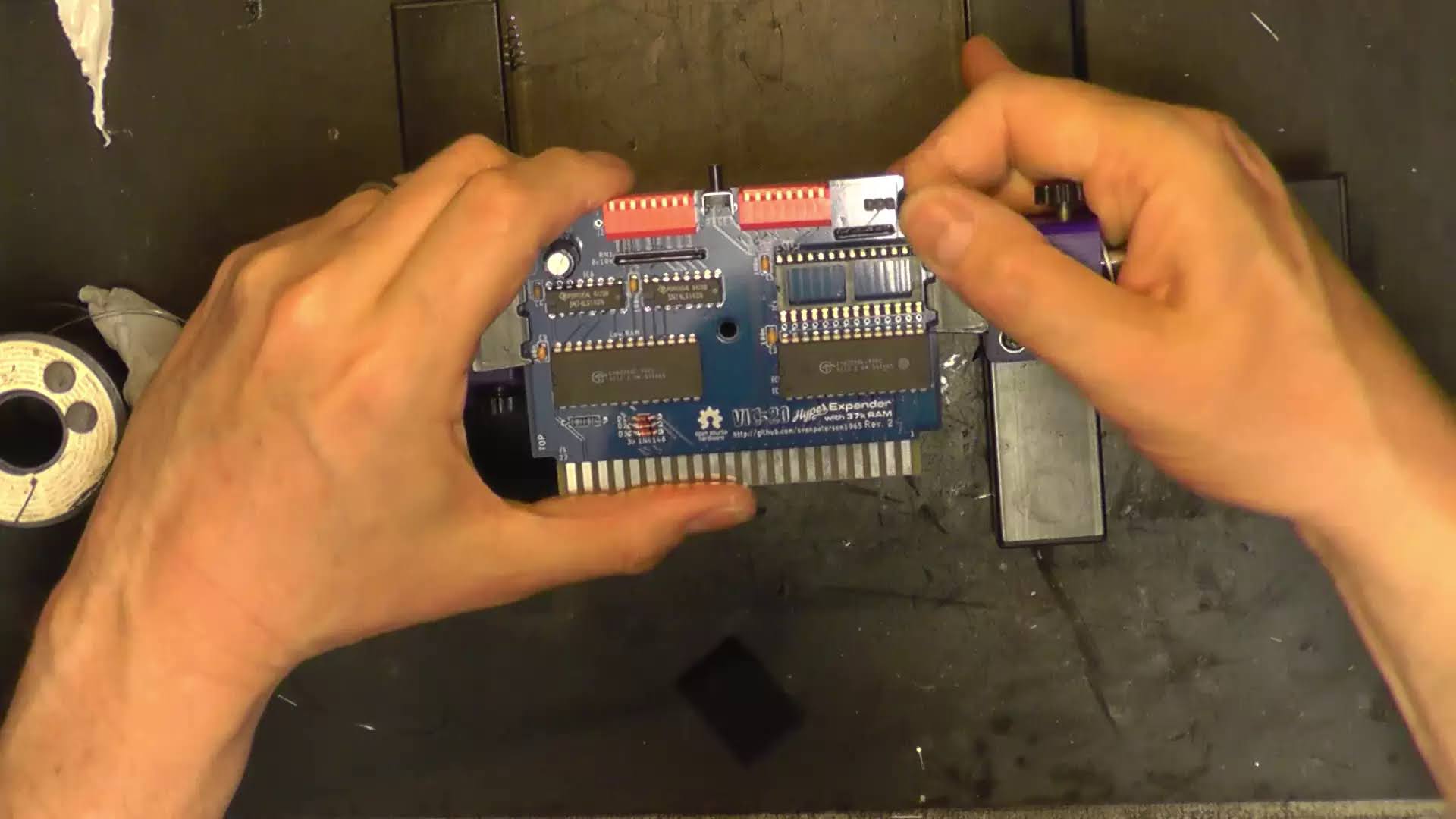
and is duly populated...


 ... and an EPROM blown with dead-test (and others) on it. 

The cartridge's dip switches are set for dead-test, and inserted. The machine is powered on... and ... ugh ... same.
Interestingly, when the cartridge's reset switch is pressed, nothing changes on screen. The reset line is again checked for operation, and, the reset line is asserted when the reset switch is depressed. Hmmm..

Some tea is consumed, and some reading up on the VIC-20's start up procedure... video 

Once the 6502 is reset, it looks to address $FFFC and starts to run code. This address is in the kernal ROM. The kernal then checks to see if a certain pattern of bytes is present on the cartridge slot, indicating a cartridge is present, and if so, jumps to $A000 (the cartridge) and runs code there, if not it runs BASIC..  So, if the fault is present with or without a cartridge, is my kernal ROM bad?

I hatch a plan. My kernal is a 901486-07, and a .bin image is available here :  http://www.zimmers.net/anonftp/pub/cbm/firmware/computers/vic20/index.html 

The TL866II plus is pressed into service, and a 27C64 EPROM is blown. There's a slight issue. The 27C64 has 4 more pins, and (obv.) a slightly different pin out. 


Thankfully a neat adaptor PCB is available form the wonderful myretrostore.co.uk


My EPROM is installed into the adaptor.... 

... and powered up ... ugh, no difference. Back to some tea and thinking. 

After reading up on VIC-20 video memory here : http://tinyvga.com/6561, it appears the VIC-20 moves it's video RAM around, depending on how much memory expansion is fitted. This isn't good news. If my video RAM were to be faulty, plugging in the hyper expander should, at the very least, alter the fault. It doesn't. Damn. This points to a faulty VIC 6561, not ideal. Despite this, I decide to check every other eventuality first. The RAM chips are scoped up. They are 2114 SRAM's. They are wired in pars, to give 1KB per pair (except UE1, which is always 512 bytes of colour RAM, regardless of expansion). 


Scoping along the IC's shows UC5, UD5, UC6 and UD6 have their CE (or CS) lines permanently high

(there's some noise there, however) ... this is not expected activity. Tracing back the schematic , these lines are fed from a 3 to 8 line decoder, a 74LS138, it's pulled out and tested. Its BAD! 

Is the VIC OK after all? After about an hour searching through all the 74 series logic I have accumulated over the years, and not finding a single 73LS138, one gets ordered! (According to my gaffer, the Germans have a word for not ever having the right chip in stock.  Fockingneinenchippenblasten. He assures me his German is excellent.). While I wait for the new chip to turn up, a socket's fitted, because that's the polite thing to do. 


A brand new 74LS138 is fitted, and no difference, until I realise I'd desoldered the wrong chip. Replacing the correct IC, and there's no difference in the fault. Damn. 


It looking more and more like the video RAM is not being addressed correctly, and that's under the control of the VIC. A brand new, old stock VIC 6561 is procured, and fitted ... and ... the fault remains. Dammit.

Suspicion is turned to the other two IC's related to the 3-8 line decoder, UC 2 & UC3 (74LS04 inverter and 74LS02 NOR) , but both test perfectly once removed. 

Could it be the RAM? It's a possibility. Now my DiagnoSys IC tester only does DRAM, not the 2114 SRAM used in the VIC, so a cunning plan is needed, and, thankfully Carsten Skjerk has beat me to the idea of using an Arduino to do the testing, so his project is implemented using an Arduino Nano. The details can be found here  https://github.com/skjerk/Arduino-2114-SRAM-tester
I elected to remove all of the RAM, test it all, and add chip sockets (it's the polite thing to do) 
The RAM all tests good, until I get to UE5 , one of the chips with the dodgy chip select line...

Gotcha! Some 2114 RAM is ordered... 


and duly arrives, and is tested prior to fitting.


A "new" 2114 is installed in UE5.. and it's switched on... a similar, but slightly different pattern of garbage appears on the screen.

UE5 was definitely faulty, but what about it's partner UD5? It passes in the tester... out of sheer desperation, I pull it from it's socket and fit a replacement IC... 

Bingo ...


So why does my tester pass it? 

I slept on that issue. The chip tester permanently shorts the CE pin to ground , and yet we'd had an issue with the CE logic ... was that why? No....
After doing some further testing, it turns out that my fault UD5 is intolerant to a slightly low voltage. The VIC's 5V rail is around 4.85V... the tester's is 5.1V ... I ran a load of tests and found that the IC starts showing errors at around 4.9V ... but here's the weird bit ... starts working correctly again around 4.75V!! By the time the voltage falls to 4.3V, it stops working again, unsurprisingly. Make a mental note to one day create a tester with a variable supply. 

So with the electronic refurbishment completed, the case is stripped down, and once the long and suffering Mrs Doz is out for the evening, it's sneaked into the dishwasher, along with the keyboard key caps. 

It comes out like a new one !


Meanwhile, the C2N datasette unit is given some attention. 

The cassette door is removed by very carefully bending the two sides in with a screwdriver. Carful with the door opening spring. It's probably best to remove it. 


The tape path is given a clean, using IPA on the heads, and capstan, and Rubber roller restorer on the pinch roller. 
The chassis is held into the case by three screws, this allows easy access to the tape counter belt, and the small take up idler. The belt is replaced, and the idler cleaned. 

After the case comes out of the dishwasher, it's placed in the sun to bleach the yellowing on the case for a few days, it comes out well... 


Meanwhile a suitable belt turns up from ebay to replace the main drive belt.


Replacement is best achieved by loosening the screw which adjusts the amount of end float the capstan flywheel has, and sliding the belt under.


The C2N is reassembled, remembering to re-fit the door spring, making sure it sits in the groove on the door. 


The VIC's motherboard is re-united with the case, and the LED and keyboard refitted


And the computer is tested .. 


Hardly taxing !


Time for a bit of retro entertainment! 


Now, you may have noticed the diagnostic ROM in the Hyperexpander wasn't working (which really would have helped!) .. and, infact the Hyperexpander wasn't really doing it's thing at all. Regardless of the settings on the dip switches, I couldn't select more than the basic 3K expansion. 

The Hyperexpander was scrutinised, and, yep... I'd stuck the High RAM chip in the EPROM hole... a rookie error. Having put this right, the Hyperexpander was re-installed. No change. The two 74LS148 chip select decoders were removed, and sure enough the low RAM one tested faulty. Having replaced that (and socketed both!) the cartridge was tested again. No change ... 

I suspected the RAM IC's may be faulty. So I built a 62256 RAM tester, in a similar fashion to the 4112 tester above (I'll detail this in a separate project) Both chips tested fine. Damn.

Everything on the hyperexpander is tested. Everything. It's all good... so the fault's in the VIC itself? It would have been easy to prove if I had another VIC-20 to test the cartridge in, but I don't... 

Back to the schematic. 


I turn my attention to what memory select lines appear at the cartridge slot.. The 3K expansion is controlled by the RAM lines, so we can safely ignore those. The other control lines, that don't appear to be functioning are BLK1,2,3 and 5. These are switched on the cartridge. They all go back to UC5, which is new. It's tested anyway, and is innocent. This IC is connected to one of the 6522's ... they're swapped over, the fault remains... The BLK1 line is traced from pin 14 of UC5 back to pin 10 of the expansion port.... except it appear on pin 10 & 11 ... removing UC5 shows there's a short circuit between pins 13 & 14 on UC5, 73LS138. A close look at the print around pin 14 shows it had lifted slightly. The socket is removed, and the print repaired. 

The short sill exists! Careful examination of the PCB, and a tiny solder bridge across two vias becomes apparent! The solder looks original ... has this fault existed since it was made? . Aggghhh .. the short is cleared. 

Bingo ... 


The motherboard is placed back in the case, and just tested before reassembly. It's dead. Wait ... whaaattt?

There's nothing on the power socket (9V AC). Sure enough the fuse in the transformer has let go! It's replaced and operation is restored... this thing hates me. 


Once it's all reassembled, the EPROM is switched in, as well as RAM. Excellent, we have everything working. About time... 


Another saved from landfill!

Saturday 5 March 2022

Wurlitzer 200A electronic piano repairs.

Ah ... another YouTube thing ... a two part thing this time! 

Enjoy


Sunday 13 February 2022

Pye 169 revisited.

Remember the Pye 169 back here?
 
Well... it's been acting up. Rather than the usual write-up, here's a bit of video entertainment, also ideal as a cure for insomnia...


Enjoy ... ! 

Wednesday 2 February 2022

Commodore 1541 Floppy Disc Drive repair.

I bought a Commodore 1541 floppy drive on eBay... not just any 1541 ... oh no... a broken one.

Apparently it was also used as a prop in a film.. http://www.computinghistory.org.uk/pages/50703/Bandersnatch/

Anyway, it doesn't work. No power.

Cursory checks to the input fuse show that's intact, so caution is thrown to the wind and mains applied... the over current trip on the bench pulls straight out (it's rated at 10A)

Checking the input fuse shows it to still be intact ..?

Ah well, in bits with it... 

Removing the main PCB allows access to the transformer etc .. 


... but what's that goop on the bottom of the PCB? 

It's waxy ... 


The mains power input couldn't be simpler. IEC Socket, fuse, switch, transformer... 


... the red seal on top of the socket looks  to have "burst" ... is that the source of our waxy goop, and excessive current draw?


Removal of the lower part of the case, and lifting the chassis out, shows more goop, right by the socket. 


The rivets securing the socket are drilled out, and it's removed.


Looks like the internal filter failed and got excessively hot at some stage, and melted the insulation. It measures a short circuit between live and neutral! A new filtered socket is obtained...


.. and duly fixed into position with some M3 fasteners. Finding a shorter socket is essential, there's just not enough room for one with tags. 


And powering up gives us the familiar sequence of LEDs, and a spinning disc. ðŸ˜Š
Now what's needed is a C64 or VIC20 to test it ... hmmmm ...

Monday 20 December 2021

Someone's been here before .... The Sony TC-377.

Jason from the record shop called.

"A mate of mine has a Sony reel to reel that's not working, can you take a look?" 

Yeah ... why not.


It's a Sony TC-377, very nice. 

A quick test, and it refuses to go into play. A common issue, usually to do with sticky grease on the selector cam, worn or perished belts, or worn or perished idlers. Rewind and fast forward are in rude health, so that rules out a couple of the idlers straight away. 

Let's get it apart.

Remove all the knobs from the front panel, they should all just pull off, except the pause lever which unscrews clockwise. Remove the head cover, and unscrew the retaining pins. Now I've smelt a rat, they're lose. They're never lose. There are also five retaining screws on the front panel, or rather there should be. One is significant by it's absence. There's one that's easy to overlook... it's by the heads. 


The front panel then lifts away. 


Four screws remove the back panel. We won't need to be in here, but if you have no motor running, or it's just humming and not turning, the chances are that silver motor run capacitor as the top has thrown in the towel, and needs replacement. It's a dual value cap, one is for use on 60Hz supplies, the other, placed in parrallel for 50Hz. You only need to get one value to replace it, unless you intend to go globe-trotting with the thing... For 50Hz operation, you'll need 2.0uF , for 60Hz 1.5uF. 


OK, we need to remove the mode selector mechanism, which is a pain. First off remove the three screws circled in red, which will allow you to remove the heads in one piece, don't undo or losen any others!!!  There are three brass spacers behind, put them somewhere safe. Now remove the four screws circled in cyan. Note here than one of mine is chewed up ... hmmmm.

You can now extract the mechanism, unhooking the levels and wiggling off the take up belt from the capstan flywheel as you go...  

Now, I expect this mechanism to be covered in gold-coloured grease, that is doing the perfect impersonation of glue. Normal procedure is to clean it all of with IPA, diassembling as required, and re-lubricating with superlube or similar.. But this has already been done. Only one issue is the cam select lever has jumped behind it's slot. It's a quick fix... 
... but it's not the end of the story. There's a couple of brake pads missing in action, and the capstan drive idler lever is seized up, so the capstan never gets drive. The idler is secured to the lever with a circlip, so that's popped off and removed.
We can't disassemble the lever, as it's riveted together, so some heat is applied to the pivot with the soldering iron, and some penetrating oil gently worked into the pivot. Eventually it starts to move, and some spray grease is eased gently in to prevent re-occurrence. The lever should move freely, and spring back into position. 

There are a few other levers on this side of the mechanism which look like they are in need of some attention, so they're sorted out, and new brake pads fabricated and fitted. 

Finally the mechanism is reassembled and tested. 

The tape has some Christmas carols on, how appropriate.


And the case is reassembled. 

Another saved from landfill!