STOP PRESS! This project is now revised and updated here, and will now create KML files, to open directly in google earth!
Now, my friend Julian and I have, for the past three years, been building a racing car. I've been lending a hand with the electrics and certain mechanical bits.
It's based on a 1971 Mini Clubman (by the name of Florence)
Here's Julian, fitting the door mirror.
After it's first season competing (with Julian at the wheel) , it's not disgraced itself at a few hillclimbs...
This video isn't mine, but this is Julian at the National Championship at Wiscombe Park late last year.
Anyway. Julian wants a bit more power, this has necessitated a new and bigger engine, and a new and bigger carburetor. In turn, the baulkhead had to be modified to accommodate the changes. Now the lovely dashboard we had created to house the instruments had to face some changes, and the large mechanical speedo had to go (when you're racing, you're not looking at how fast you're going!)
We looked for a small speedo that would suit our requirements, but I mooted the idea of a digital speedo, collecting it's data from a GPS receiver... I have previously used U-blox receivers and chipsets commercially, so I ordered one from the lovely people at Hobby Components here.
Excellent. Provides updates at up to 5 times per second.
Now, this coupled to an Arduino pro-mini, and a nice OLED display would provide a nice speedo...
The display is a 128x64 SDD1306 OLED display, and was purchased from eBay.
Then I got to thinking ... what if I could log some data to an SD card as well... might provide some interesting data for when the car is racing. So I ordered an SD card reader at the same time ...
eBay is once again our friend!
Now first things first, we need to configure our GPS receiver. This is done by hooking up the receiver board to our PC (I used the same FTDI converter I use to program the Pro-mini boards).
Go and get yourself a copy of uCenter from the U Blox website here.
Now when the software opens, you will need to tell it which com port and baud rate the receiver is on. Click on the receiver tab, and select the com port. Try 9600 for the baud rate, if you see no data, try another speed. Soon enough you should see some data from the receiver.
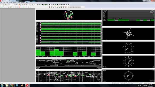
Amazing, isn't it!
Now click View and Messages View. Maximise the messages window.
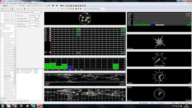
Now scroll down to UBX and click it to expand the tree. Click on CFG . Now click on RATES and change the Measurement Period to 200mS.
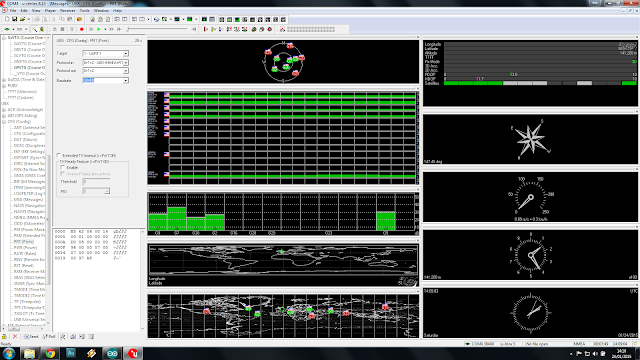
Now expand the PORTS section, and change the baudrate to 57600. Once you do this, uCenter will lose communications with the receiver module. Go to Receiver, and re-set the baudrate to 57600.
Now click on Receiver again, selection Action and click Save Config.
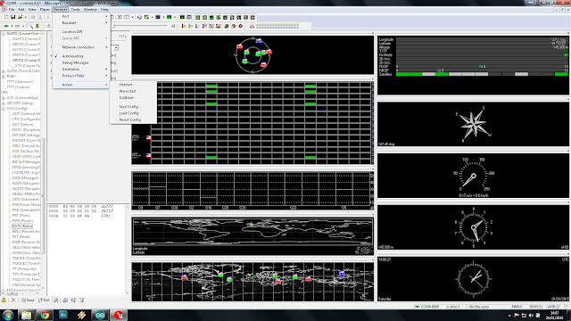
You can now disconnect the receiver from the PC.
Now, a word about power. The uBlox receiver is happy at 3.3 or 5v, The Pro-mini I've got is good at 3.3v or 5v, the display works great on 3.3v or 5v... the SD Card reader, whilst it has a pin marked 5v, is only happy with 3.3v on it's data and clock pins. The 5v is purely to power the on-board 3.3v regulator. Now, we can either run everything from 5v and use a level converter between the arduino and the SD card reader (stupid) , or we can use the 3.3v from the card reader's on board reg to drive everything else (a really good idea!)
So, from the car our 12v is dropped to 5v using an ordinary 7805 voltage regulator, this is then supplied to the SD Card reader. The 3.3V pin on the card reader then supplies power to the arduino, the GPS receiver and the display.
SDA on the display is connected to A4, SDC to A5. The SD card interface is connected to pins 4 (CS), 11 (MOSI), 12 (MISO) & 13 (SCK).
A toggle switch is connected between pin 9 and ground. The toggle switch is used to switch on and off the logging feature.
The GPS receiver's TX pin is simply coupled to the hardware RX pin on the arduino, but not until we've uploaded the software!
Now there is an excellent library to control the display from Adafruit, but it is very memory intensive, and somewhat slow. This caused difficulty in writing to the SD card in time.
After spending a while surfing, I happened upon a lightweight library at http://blog.oscarliang.net/arduino-oled-display-library/ which is perfect, although it's not designed for this display. There's a requirement to enable the on-board inverter in our sketch.
We'll also need the most excellent TinyGPSPlus library from https://github.com/mikalhart/TinyGPSPlus
The SD card will need to be formatted on your Windows PC as FAT32. Open notepad and save a blank file as gps.txt to the card.
Here's the schematic:-
You will notice there's a zener diode before the 7805, this to clamp any nasties that might be present on our 12V supply from the vehicle (usually on cranking). Any value between 18 and 32 volts will do.
Lashed up for testing...
 7805 power supply.
Will it all fit in the box?
Of course ;)
Painted black to match the dash.
Not many satellites being received on the bench!
But a few in the window!
The receiver is actually very sensitive, although initial lock may take a few minutes, once recent data is stored in the receiver's non-volatile memory, warm starts are very quick indeed.
Out for a quick test run, and logged some data....
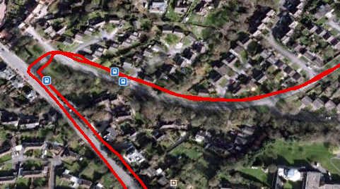 It's pretty easy to import the txt file into google maps, and get some useful data...
Here, individual data points are shown, each showing the speed at that point.
Anyway, here's the sketch....
/*
Fast GPS data logger.
(c) 14th February 2015 A.G.Doswell

Released to all and sundry under GNU License.

The sketch uses a U-Blox 6M GPS satellite module connected to the hardware serial interface,
a 128x64 SDD1306 OLED display module connected as an I2C device to pins A4 (SDA)& A5 (SCL) and an SD card interface
connected to pins 4 (CS), 11 (MOSI), 12 (MISO) & 13 (SCK) The arduino used is a Nano with 3.3v ATMEGA328P.
Warning - Many SD card interfaces are not 5V.
There's a toggle switch which connects pin 9 to GND for Record.
Data is written to the card an impressive 4 times per second, in real-time.

The OzOled library is not quite "right" for this application, but works, and is lightweight and fast enough. Thanks Oscar!
It is available here : http://blog.oscarliang.net/arduino-oled-display-library/
TinyGPSPlus is available here :https://github.com/mikalhart/TinyGPSPlus

*/

#include <SPI.h>
#include <Wire.h>
#include <OzOLED.h>
#include <TinyGPS++.h>
#include <SD.h>

static const uint32_t GPSBaud = 57600;
int SatVal;                        // Number of satellites locked
int Speed;                         // Speed in MPH
char SpeedA [4];                   // Speed as char
TinyGPSPlus gps;                   // Feed gps data to TinySGPSPlus
File myFile;                       // Start SD
int speedDigit;                    // Number of digits in Speedo display
boolean card;                      // Is there a card present?
boolean rec = false;               // Is the record switch low? (false = high)
int recPin = 9;                    // Record pin (Pull low to record data)

void setup()   {

  Serial.begin(GPSBaud);           // Start GPS serial comms
  pinMode (recPin, INPUT_PULLUP);  // recPin as input and pulled high
  OzOled.init();                   // initialze SDD1306 OLED display
  OzOled.sendCommand(0x8d);        // Set displays inbuilt inverter on
  OzOled.sendCommand(0x14);
  OzOled.setBrightness(0xFF);      // ... and brightness to max
  OzOled.clearDisplay();           // Clear the screen
  OzOled.setNormalDisplay();       // Set display to Normal mode
  pinMode(10, OUTPUT);             // CS for SD card, wether it likes it, or not.
  OzOled.clearDisplay();


  if (!SD.begin(4)) {              //Check SD card is present
      OzOled.printString("SD card fail    ",0,7);
      card = false;
      }
      else {
      OzOled.printString("SD card OK      ",0,7);
      card = true;
      }

  OzOled.printString("Sats:",0,0);  // Set up display
  OzOled.printString("Speed:",0,1);
  OzOled.printString("MPH",7,6);
}

void loop() {
    while (Serial.available() > 0) //While GPS message received
    if (gps.encode(Serial.read()))
      displayInfo();
}

void displayInfo() {               // Display the data
  SatVal = int(gps.satellites.value());
  Speed = int(gps.speed.mph());
  itoa (Speed,SpeedA,10);
  OzOled.printNumber ((long)SatVal,6,0);
  OzOled.printBigNumber (SpeedA, 7,1);
  speedDigit = strlen(SpeedA);    // get length of Speed , and delete left behind zero if req'd
  if (speedDigit == 1) OzOled.printBigNumber(" ",10,1);
  if (digitalRead(recPin) == HIGH && card == true) { //If the record switch is high and the card is OK, write card data
    rec = true;
    OzOled.printString("SD card OK REC",0,7);
  }
  if (digitalRead(recPin) == LOW && card == true) {
    rec = false;
    OzOled.printString("SD card OK    ",0,7);
  }

  if (card==true && rec==true) {
    writeInfo(); //write the data to the SD card
  }
  smartDelay(200);

}

// This custom version of delay() ensures that the gps object
// is being "fed".
static void smartDelay(unsigned long ms)
{
  unsigned long start = millis();
  do
  {
    while (Serial.available())
      gps.encode(Serial.read());
  } while (millis() - start < ms);
}

void writeInfo() { //Write the data to the SD card Date,Time,Lat,Long,Spped (MPH) and number of satellites locked

  myFile = SD.open("gps.txt", FILE_WRITE);
  if (myFile) {
    myFile.print(gps.date.month());
    myFile.print(F("/"));
    myFile.print(gps.date.day());
    myFile.print(F("/"));
    myFile.print(gps.date.year());
    myFile.print(F(","));
    if (gps.time.hour() < 10) myFile.print(F("0"));
    myFile.print(gps.time.hour());
    myFile.print(F(":"));
    if (gps.time.minute() < 10) myFile.print(F("0"));
    myFile.print(gps.time.minute());
    myFile.print(F(":"));
    if (gps.time.second() < 10) myFile.print(F("0"));
    myFile.print(gps.time.second());
    myFile.print(F(","));
    myFile.print(gps.location.lat(), 6);
    myFile.print(F(","));
    myFile.print(gps.location.lng(), 6);
    myFile.print(F(","));
    myFile.print(gps.speed.mph(),1);
    myFile.print(F(","));
    myFile.println(gps.satellites.value());
 // close the file:
    myFile.close();
  }
}


Hello
ReplyDeleteGreat work.
I did this project and after finishing it i wanted to see the file stored in the memory
card but i dont know hw to import the file to g maps.
If you ould help me i would be thankfull.
Best Regard
Isad
Hi Isad. I use the website http://www.convertcsv.com/csv-to-kml.htm. This will convert the CSV file from the card into a KML file, which you can open in Google Earth. Google Earth is much less restrictive. Let me know how you get on! Andy
ReplyDeleteHi, Andy. I'm a newer user of Arduino. In your comments, inside Sketch, you told that pin 4 of Pro Mini was coneccted do CS in SD Card, but your programming code show pin 10, Am I wrong? Wich pin did you connect to CS or in SD Card? Both of them will work fine? Thanks. LM.
ReplyDeleteLM... You're right, and have spotted my deliberate mistake (ahem).. connect you CS line to D10! If you look at the naming of the pins, you can see why I made the mistake on the diagram. It was probably late at night when I did it! Let me know how you get on!
ReplyDeleteThanks!
Andy
Thanks, Andy. The sketch code is right (only the comments in code and diagram need changes). Why did you use naming J1.1, J1.2....J2.1...in your diagram? Can you tell me what means J1.4 and J2.2 (named COM) connect to GND in Pro Mini? Thanks again. LM.
ReplyDeleteHi LM.
ReplyDeleteThe Eagle library I used (before I picked up on the excellent Sparkfun library) named them this way. I think it refers to J1 being the connector, and the .1 ,.2 etc being the pin number.
Hope this helps.
Hi, Andy. Finally, all the itens arrived and I was able to mount this "project". It works great. Initially, I used 9600 for GPS baud (changing the code of YOUR sketch). It worked. Do you think that changing to 57600, using Ucenter, it will work better (faster and, maybe, more accurated)? My GPS is very similiar of yours. I will put this "project" in my radio airplane to save the route. I'm flying about 8 km, with fpv (of course), but the system that I use doesn't save the route in file (coordinates). I think that your project will help me. Thank you very much. LM.
ReplyDeleteHi LM,
DeleteDamn I've had trouble trying to comment on my own blog!!! (fixed it now!). Right....
With regards to your 9600 baud rate, If you are getting the required amount of points logged on the card, then there's little point in upping the rate. I was concerned that 9600 wasn't going to be quick enough to get the data from the GPS, process it and write it to the card, but if it works for you! You should be seeing 5 points logged per second. Backing off the "rate" setting in uCenter will give better accuracy in theory, but I've not seen much of a difference if the receiver has a good view of the sky and has a good few satellites locked.
With regards to the file produced, and the use of uCenter, have you seen the latest update I did ? http://andydoz.blogspot.co.uk/2016/08/arduino-fast-gps-datalogger-with.html
This automatically configures the receiver in runtime, so you don't need uCenter at all. It also has a function to set the speed units, and produces a KML file on the card which you can open in google earth without all that tedious messing about.
One word about SD cards. Don't use the formatter built in to your OS. Use the program here: https://www.sdcard.org/downloads/formatter_4/
If you don't use this formatter, it seems to slow the card down, to the extent incorrect characters are written, corrupting the KML.
Have fun, and send me some pictures!
Thanks,
Andy
Thank you for sharing the new version. I changed some things in your older version, to obtain speed in kmph and to log altitude too...well, thank you for comments, sugestions and big expertise...I'm here to learn. See you. Tks. LM.
DeleteDear Andy. I set the Measurement Period to 200ms and the the baudrate to 57600, using u-center. It worked fine until I disconnect the GPS module. When I connect it again, the values return to 1000ms and 9600 in baudrate. Do you know what is happening? It is like a ram memory, when I restart the module, it returns to original values (1000ms and 9600). Thank you.
ReplyDeleteCheck out this .... http://andydoz.blogspot.co.uk/2016/08/automatic-configuration-of-ublox-m6-gps.html
DeleteYa, this is now in your "new" version of sketch....Really, the ram behavior....Thanks again. LM.
ReplyDelete