Ryan's Dad lives in Australia, and Ryan wanted to make a version of the fast GPS datalogger that his dad could use on is boat.
After sorting out the problems Ryan had with his U-blox GPS module here, we set about a few mods.
Firstly, was to be able to select the units of speed selectable when the unit first starts up. The sketch now looks for a button, connected between A3 and ground. This allows the unit to be set for KPH (Kilometres per hour), KTS (knots) and MPH (Miles per hour). This is selected by the new void configureUnits. It times out after a couple of seconds. The configureUnits void sets a flag, which selects which type of data is written to the Speed variable, and written to both the display and the card.
Here's Ryan's version, bread-boarded and tested on the bench.
Here's the new schematic, showing the addition of the "Select units" switch, and the extra connection to the GPS module to allow us to set the Ublox receiver's configuration.
Now Updated (again) with selectable speed units, and configuration of U-blox GPS in runtime, avoiding the need to use U-Center to configure the receiver. Click Here!
The fast GPS datalogger project is the most popular project on here. Link.
It's been working well on the race car since it's inception, and has provided some really useful data to improve the performance of the driver!
What isn't so great is how the data is stored. It stores everything, regardless of fix, number of races etc, so it's a headache to filter out each race, and remove useless invalid data, either without a time stamp or valid position or speed, and then turn it into something that could be used. I have been painstakingly converting the data into KML, which we can directly read with mapping software, such as Google Earth.
I've made some modifications to the software to sort out some of these issues... here's the new features:
Each time the record switch is pressed, valid GPS data is required, and once obtained, a new file name is created from the current time, HHMMSSCC.kml (in UTC, CC representing centiseconds here), and the KML header file is written.
Now the file is built as in the previous version, except this time in KML format.
Speeds below 5 MPH are not recorded.
When record is switched off, the KML file is completed and closed.
So once the card is removed from the unit, simply read the kml file from the card, and open in google earth.
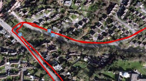
So I went out for a quick jaunt in England's green and pleasant....
... and loaded the KML file straight into google earth.
No more tedious editing required!
No changes to the hardware are required. Just remember to disconnect the RX line from the GPS module when attempting to load the new sketch.
STOP PRESS! This project is now revised and updated here, and will now create KML files, to open directly in google earth!
Now, my friend Julian and I have, for the past three years, been building a racing car. I've been lending a hand with the electrics and certain mechanical bits.
It's based on a 1971 Mini Clubman (by the name of Florence)
Here's Julian, fitting the door mirror.
After it's first season competing (with Julian at the wheel) , it's not disgraced itself at a few hillclimbs...
This video isn't mine, but this is Julian at the National Championship at Wiscombe Park late last year.
Anyway. Julian wants a bit more power, this has necessitated a new and bigger engine, and a new and bigger carburetor. In turn, the baulkhead had to be modified to accommodate the changes. Now the lovely dashboard we had created to house the instruments had to face some changes, and the large mechanical speedo had to go (when you're racing, you're not looking at how fast you're going!)
We looked for a small speedo that would suit our requirements, but I mooted the idea of a digital speedo, collecting it's data from a GPS receiver... I have previously used U-blox receivers and chipsets commercially, so I ordered one from the lovely people at Hobby Components here.
Excellent. Provides updates at up to 5 times per second.
Now, this coupled to an Arduino pro-mini, and a nice OLED display would provide a nice speedo...
The display is a 128x64 SDD1306 OLED display, and was purchased from eBay.
Then I got to thinking ... what if I could log some data to an SD card as well... might provide some interesting data for when the car is racing. So I ordered an SD card reader at the same time ...
eBay is once again our friend!
Now first things first, we need to configure our GPS receiver. This is done by hooking up the receiver board to our PC (I used the same FTDI converter I use to program the Pro-mini boards).
Go and get yourself a copy of uCenter from the U Blox website here.
Now when the software opens, you will need to tell it which com port and baud rate the receiver is on. Click on the receiver tab, and select the com port. Try 9600 for the baud rate, if you see no data, try another speed. Soon enough you should see some data from the receiver.
Amazing, isn't it!
Now click View and Messages View. Maximise the messages window.
Now scroll down to UBX and click it to expand the tree. Click on CFG . Now click on RATES and change the Measurement Period to 200mS.
Now expand the PORTS section, and change the baudrate to 57600. Once you do this, uCenter will lose communications with the receiver module. Go to Receiver, and re-set the baudrate to 57600.
Now click on Receiver again, selection Action and click Save Config.
You can now disconnect the receiver from the PC.
Now, a word about power. The uBlox receiver is happy at 3.3 or 5v, The Pro-mini I've got is good at 3.3v or 5v, the display works great on 3.3v or 5v... the SD Card reader, whilst it has a pin marked 5v, is only happy with 3.3v on it's data and clock pins. The 5v is purely to power the on-board 3.3v regulator. Now, we can either run everything from 5v and use a level converter between the arduino and the SD card reader (stupid) , or we can use the 3.3v from the card reader's on board reg to drive everything else (a really good idea!)
So, from the car our 12v is dropped to 5v using an ordinary 7805 voltage regulator, this is then supplied to the SD Card reader. The 3.3V pin on the card reader then supplies power to the arduino, the GPS receiver and the display.
SDA on the display is connected to A4, SDC to A5. The SD card interface is connected to pins 4 (CS), 11 (MOSI), 12 (MISO) & 13 (SCK).
A toggle switch is connected between pin 9 and ground. The toggle switch is used to switch on and off the logging feature.
The GPS receiver's TX pin is simply coupled to the hardware RX pin on the arduino, but not until we've uploaded the software!
Now there is an excellent library to control the display from Adafruit, but it is very memory intensive, and somewhat slow. This caused difficulty in writing to the SD card in time.
After spending a while surfing, I happened upon a lightweight library at http://blog.oscarliang.net/arduino-oled-display-library/ which is perfect, although it's not designed for this display. There's a requirement to enable the on-board inverter in our sketch.
The SD card will need to be formatted on your Windows PC as FAT32. Open notepad and save a blank file as gps.txt to the card.
Here's the schematic:-
You will notice there's a zener diode before the 7805, this to clamp any nasties that might be present on our 12V supply from the vehicle (usually on cranking). Any value between 18 and 32 volts will do.
Lashed up for testing...
7805 power supply.
Will it all fit in the box?
Of course ;)
Painted black to match the dash.
Not many satellites being received on the bench!
But a few in the window!
The receiver is actually very sensitive, although initial lock may take a few minutes, once recent data is stored in the receiver's non-volatile memory, warm starts are very quick indeed.
Out for a quick test run, and logged some data....
It's pretty easy to import the txt file into google maps, and get some useful data...
Here, individual data points are shown, each showing the speed at that point.
Anyway, here's the sketch....
/*Fast GPS data logger.(c) 14th February 2015 A.G.DoswellReleased to all and sundry under GNU License.The sketch uses a U-Blox 6M GPS satellite module connected to the hardware serial interface, a 128x64 SDD1306 OLED display module connected as an I2C device to pins A4 (SDA)& A5 (SCL) and an SD card interface connected to pins 4 (CS), 11 (MOSI), 12 (MISO) & 13 (SCK) The arduino used is a Nano with 3.3v ATMEGA328P.Warning - Many SD card interfaces are not 5V. There's a toggle switch which connects pin 9 to GND for Record.Data is written to the card an impressive 4 times per second, in real-time. The OzOled library is not quite "right" for this application, but works, and is lightweight and fast enough. Thanks Oscar!It is available here : http://blog.oscarliang.net/arduino-oled-display-library/TinyGPSPlus is available here :https://github.com/mikalhart/TinyGPSPlus*/
#include <SPI.h>
#include <Wire.h>
#include <OzOLED.h>
#include <TinyGPS++.h>
#include <SD.h>
staticconst uint32_t GPSBaud = 57600;
int SatVal; // Number of satellites lockedint Speed; // Speed in MPHchar SpeedA [4]; // Speed as charTinyGPSPlus gps; // Feed gps data to TinySGPSPlusFile myFile; // Start SDint speedDigit; // Number of digits in Speedo display boolean card; // Is there a card present?boolean rec = false; // Is the record switch low? (false = high)int recPin = 9; // Record pin (Pull low to record data) voidsetup() {
Serial.begin(GPSBaud); // Start GPS serial commspinMode (recPin, INPUT_PULLUP); // recPin as input and pulled high
OzOled.init(); // initialze SDD1306 OLED display
OzOled.sendCommand(0x8d); // Set displays inbuilt inverter on
OzOled.sendCommand(0x14);
OzOled.setBrightness(0xFF); // ... and brightness to max
OzOled.clearDisplay(); // Clear the screen
OzOled.setNormalDisplay(); // Set display to Normal modepinMode(10, OUTPUT); // CS for SD card, wether it likes it, or not.
OzOled.clearDisplay();
if (!SD.begin(4)) { //Check SD card is present
OzOled.printString("SD card fail ",0,7);
card = false;
}
else {
OzOled.printString("SD card OK ",0,7);
card = true;
}
OzOled.printString("Sats:",0,0); // Set up display
OzOled.printString("Speed:",0,1);
OzOled.printString("MPH",7,6);
}
voidloop() {
while (Serial.available() > 0) //While GPS message receivedif (gps.encode(Serial.read()))
displayInfo();
}
void displayInfo() { // Display the data
SatVal = int(gps.satellites.value());
Speed = int(gps.speed.mph());
itoa (Speed,SpeedA,10);
OzOled.printNumber ((long)SatVal,6,0);
OzOled.printBigNumber (SpeedA, 7,1);
speedDigit = strlen(SpeedA); // get length of Speed , and delete left behind zero if req'dif (speedDigit == 1) OzOled.printBigNumber(" ",10,1);
if (digitalRead(recPin) == HIGH && card == true) { //If the record switch is high and the card is OK, write card data
rec = true;
OzOled.printString("SD card OK REC",0,7);
}
if (digitalRead(recPin) == LOW && card == true) {
rec = false;
OzOled.printString("SD card OK ",0,7);
}
if (card==true && rec==true) {
writeInfo(); //write the data to the SD card
}
smartDelay(200);
}
// This custom version of delay() ensures that the gps object// is being "fed".staticvoid smartDelay(unsignedlong ms)
{
unsignedlong start = millis();
do
{
while (Serial.available())
gps.encode(Serial.read());
} while (millis() - start < ms);
}
void writeInfo() { //Write the data to the SD card Date,Time,Lat,Long,Spped (MPH) and number of satellites locked
myFile = SD.open("gps.txt", FILE_WRITE);
if (myFile) {
myFile.print(gps.date.month());
myFile.print(F("/"));
myFile.print(gps.date.day());
myFile.print(F("/"));
myFile.print(gps.date.year());
myFile.print(F(","));
if (gps.time.hour() < 10) myFile.print(F("0"));
myFile.print(gps.time.hour());
myFile.print(F(":"));
if (gps.time.minute() < 10) myFile.print(F("0"));
myFile.print(gps.time.minute());
myFile.print(F(":"));
if (gps.time.second() < 10) myFile.print(F("0"));
myFile.print(gps.time.second());
myFile.print(F(","));
myFile.print(gps.location.lat(), 6);
myFile.print(F(","));
myFile.print(gps.location.lng(), 6);
myFile.print(F(","));
myFile.print(gps.speed.mph(),1);
myFile.print(F(","));
myFile.println(gps.satellites.value());
// close the file:
myFile.close();
}
}
<Deep voice over> Just when you thought it was safe to go into the attic</Deep voice over>
Just when you thought the project was over (and it is really!) someone comes along and puts an idea in your head... "Hey, Andy, Why don't you log the data, and make some nice graphs" ... and, in reality, why would I want to .... because
a) I'm erring on the side of geeky
and
b) Because I can...
So, what's needed...
A scrappy old Windows box ... yes, this is just the ticket , 500 MB of RAM, 900MHz processor, 100MB HDD ... more than enough for the job.
Another arduino board, another receiver and some code. (I suppose you could use your exisiting display, and just add the Serial.print bits to that code if you wished. Mine's all nicely boxed up, so it had to be stand alone)
// Receiver Sketch for Dehumidifier controller project// Written by A.G.Doswell 08 Aug 2014// Receiver connected to pin 9
#include <VirtualWire.h>
#include <VirtualWire_Config.h>
int TX_ID =10;
int Temp;
int Humidity;
int Dew;
boolean Output;
char buffer[5];
int led = 13;
voidsetup() {
pinMode(led, OUTPUT);
//Comms set upSerial.begin(9600);
// Virtualwire setup
vw_set_tx_pin(10); // Even though it's not used, we'll define it so the default doesn't interfere with the LCD library.
vw_set_rx_pin(9); // RX pin set to pin 9
vw_setup(300); //sets virtualwire for a tx rate of 300 bits per second, nice and slow!
vw_rx_start();
}
voidloop()
{
typedef struct rxRemoteData //Defines the received data, this is the same as the TX struct
{
int TX_ID;
int Temp;
int Humidity;
int Dew;
boolean Output;
};
struct rxRemoteData receivedData;
uint8_t rcvdSize = sizeof(receivedData);
if (vw_get_message((uint8_t *)&receivedData, &rcvdSize))
{
if (receivedData.TX_ID == 10) { //Only if the TX_ID=10 do we process the data.int TX_ID = receivedData.TX_ID;
int Temp = receivedData.Temp;
int Humidity = receivedData.Humidity;
int Dew = receivedData.Dew;
boolean Output = receivedData.Output;
digitalWrite(led, HIGH);
// writes the received data to the serial interfaceSerial.print("#S|DATA|[");
Serial.print(itoa((Humidity), buffer, 10));
Serial.print(";");
Serial.print(itoa((Temp), buffer, 10));
Serial.print(";");
Serial.print(itoa((Dew), buffer, 10));
Serial.println("]#");
digitalWrite(led, LOW);
}
}
}
// End of file
So there it is. Load that into your favorite arduino, and connect a receiver to pin 9.
Now we need to tell Gobetwino what to do when it sees data from the com port. Firstly, quit the Arduino IDE. The two can't be running at the same time, or Gobetwino can't access the serial port the arduino is chatting on.
Firstly click on Commands.
Then click the New Command button. Using the drop down box , select LGFIL (Log data to file). Give it the Command name DATA (must be in capitals to match our Arduino data). Now create a blank data.txt file somewhere, using Windows explorer, just right click on a directory, click new and Text document. Name it data.txt. I chose the root of C: here for ease, but it can be anywhere....
Now back to Gobetwino. Click on the browse button, and point it to our freshly created data.txt file.
Check the Time stamp box.
Click on save, and click on settings. Now click the serial port tab, and select the serial port our Arduino is communicating on. This is the same port the Arduino IDE was using.
Now every time the Arduino receives data from our transmitter, it will blink it's LED breifly, and send the data to Gobetwino, which will add a time stamp, and save it dutifully to the data.txt file.
You should end up (after a while) with a txt file looking a bit like this....
08/08/2014 16:13:15;28;36;14
08/08/2014 16:13:36;29;38;16
08/08/2014 16:13:58;29;38;16
08/08/2014 16:14:19;28;36;14
08/08/2014 16:14:40;28;36;14
08/08/2014 16:15:01;29;38;16
08/08/2014 16:15:22;28;36;14
08/08/2014 16:15:43;29;38;16
08/08/2014 16:16:04;29;38;16
08/08/2014 16:16:26;29;38;16
08/08/2014 16:16:47;29;38;16
08/08/2014 16:17:08;29;38;16
08/08/2014 16:17:29;29;38;16
08/08/2014 16:17:50;29;38;16
08/08/2014 16:18:11;28;36;14
08/08/2014 16:18:33;29;38;16
08/08/2014 16:18:54;29;38;16
08/08/2014 16:19:15;29;38;16
08/08/2014 16:19:36;29;38;16
08/08/2014 16:19:57;29;38;16
08/08/2014 16:20:18;29;38;16
08/08/2014 16:20:39;29;38;16
08/08/2014 16:21:01;28;36;14
08/08/2014 16:21:22;28;36;14
08/08/2014 16:21:43;28;36;14
08/08/2014 16:22:04;29;37;15
Now if we make a copy of the file, and change the extension to .csv (if windows worries about this making our file unusable, just carry on regardless!) It will then open in the spreadsheet programme of your choice (I choose OpenOffice), and with a little charting, we can create our graph...
Yes well, that's all very nice 'an 'all.... but wouldn't it be nice if the data was sent to me?
I'm not going to go into this in detail... as it took me hours to get it to work, and I'm still not really sure how I got it all to work... but there's a very useful piece of software called Sendemail available here: http://caspian.dotconf.net/menu/Software/SendEmail/ that I configured using the usual Windows task scheduler to copy the file, email me the copy, and then install a new blank in it's place... and it works a treat!
 Here's Ryan's version, bread-boarded and tested on the bench.