Translate

Showing posts with label Turntable. Show all posts

Friday 17 April 2020

Garrard Zero 100. From Zero to Hero.

Many moons ago, I was seduced by this oddball Garrard turntable.


It's that weird pantograph arm. It should track perfectly. I spotted this one, at one of those audio jumble meets. It's missing a lever or two, and the selector switches are sort of hanging there, the plinth battered and bruised.. £18 and it followed me home, much to the delight of the long and suffering Mrs Doz.

It's seen a bit of action. There's the usual "Garrard glue" to deal with, but the main issues are with the control switches...

There's some sort of mounting bracket missing or broken.

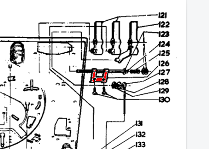
A quick look at the exploding diagram shows it's no 126...


I managed to score a few parts on eBay, but sadly not the bracket. Those levers are in better nick than mine though...

So a suitable bit of steel was cut and filed to shape...

That looks like it should do the job. There's an issue though. The screws originally fitted into the plastic top plate, where there's a reinforced bit. It's broken off...
I removed the levers (I wanted to change them anyway), and put some epoxy down to build up a layer to support the screws. 
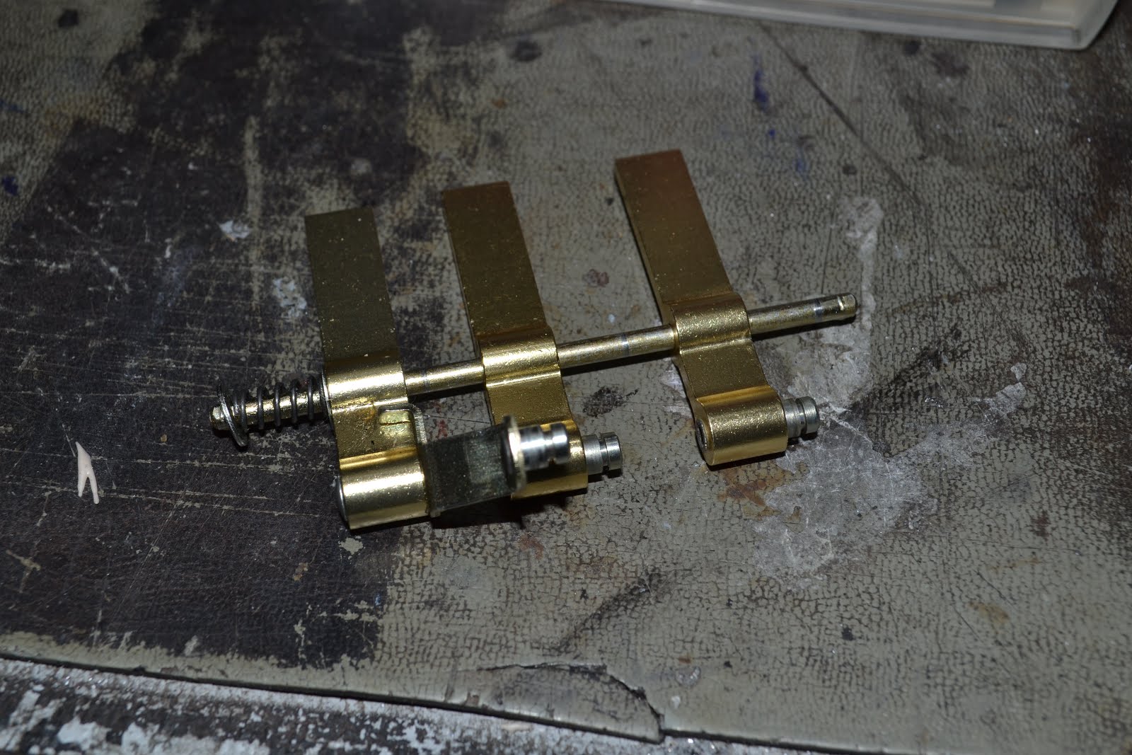
and while that's going off, I swap the levers over, and sort out removing the sticky grease from the rest of the mechanism.. 
The speed change detent arm was exceptionally seized up, and required plenty of heat to get it to free up.


Once the epoxy had cured it was flattened off, and it was at this point I realised that the top plate was no longer secured to the chassis. as again there were sheered off screw fittings... a change of tack was required, there just isn't enough strength here......


The bracket is reversed, and bonded to the chassis with some of the UV cure adhesive I've tried before... now I take it the UV has only cured the outside part, but it seems to be holding. Where the plastic top plate is broken off, I used the glue gun to fill the void, and fit a screw through my previous epoxy repair to secure the top plate at the other side. The clamp is simply holding the top plate flush.


... and the following morning, all the gluing seems to be very strong... good. Pretty it isn't, but it's now at least functional.


The deck is flipped back over, and the platter removed, by removing the rubber mat, and removing the wire clip securing the centre spindle.


The platter itself has the strobe markings on it's underside...


... which are viewed via a mirror in the "subterranian" strobe housing. It'll need removing to clean the mirror.


Two screws either side, and it drops down...


 ... and we can clean the mirror. The small plastic window can also be removed and cleaned.


A quick note on how the speed adjust works.
The manual speed adjustment knob under the speed selector operates a lever, which moves the idler up and down a tapered section on the motor drive shaft, thus changing the speed. A bit "lenco" really...


There's more grease to be cleaned up and replaced on the top. This lever is seized solid, and, once again, needed a bit of hot air to tempt it off.

The motor mounts are still supple, as is the idler, so that's good news.


Now to the Zero 100's arm. This is what interests me about this turntable ... it gives it it's name, Zero tracking error. The headshell actually moves as the arm moves across the record, removing the error. This one is horribly wobbly. Now because the headshell is articulated, it's never going to be the stiffest tonearm, but this is wobbling around from the pivot end.


One screw removes the perspex gimbal surround, allowing a better view.


Sure enough a tiny screw is missing, which secures the arm tube to the bearing. A replacement is found, dropped, lost and found again before being fitted.


Now the arm is given a quick buff up to remove the worst of the corrosion on it's surface, and the brass cover on the counterweight is treated likewise.. Looking quite smart now :)


Fitting a cartridge. Now the Zero 100, in common with a few other Garrard decks of the time uses a convenient cartridge slide. Convenient that is, if you happen to have one... I knew mine was missing, so I'd previously stopped into my favourite purveyor of Garrard bits, and managed to procure a new-old-stock slide. The contacts are a bit tarnished, but that'll soon clean up.


My friend John had sent me a previously enjoyed AT95 a while back, so that was mounted onto the slide...


Normally the Zero 100 came with a perspex alignment gauge, that slid over the slider, and you just set your stylus onto the cross-hairs, and all is done. Obviously this was long-gone. As our arm compensates for any tracking error, using a conventional protractor and setting Stevenson, Baerwald etc is irrelevant.  After nearly starting a fight on a Garrard forum (some people eh?)  I hatched a plan... the arm should track something near parallel, so all I need is a line from the centre spindle out, move it about until our cartridge is on the line, move the arm in and out, and set the cartridge position so the line is followed.

A piece of cotton is pressed into service, and the cartridge position set. There is a light curve to the track, however.

Tracking weight and anti-skate are set up as per the manual.


And successfully plays through the workshop test LP, scratched and warped though it may be.


Now to think about doing something to tidy up the plinth.

Friday 25 October 2019

Hitachi HT-L33 turntable repairs.

I was given this by a kindly benefactor...


It's a Hitachi L33 turntable from about 1982.

"It plays too fast, I've tried to adjust the speed, 33 is just about OK, but 45 is wrong"

Great, this will do as a gift to my mate Alan, who's been on the lookout for a sensible small turntable for a while.

I check both speeds, which seem to be far too fast, and varying badly.

Here's the speed circuit from the manual...

The motor PWB (printed wiring board, don't ya know!) is housed inside the motor. It's a brushed DC motor, controlled by a small regulator on the board. Normally the speed is adjustable via a small hole, operating a pot inside the motor. In this case, that connection is made available outside the motor, via the orange wire.

The speed is first set to 33 RPM, whereby the FET Q01 is switched on by the micro processor, and is effectively short circuiting R42 (the 45RPM control) and R41. Once R40 (33 RPM control) is set, you can then adjust 45. Doing it the other way round won't work, as 33 RPM will also adjust 45! The whole motor and speed arrangement is fed by a regulated 9.9V supply from Q11. Q10 is there to rapidly bring the motor up to speed, under control from the micro.


OK, the pots are already set to minimum speed. Damn... why so fast ?

Incidentally, be careful to secure the platter in place with some tape (or remove it) before turning this upside down. If you don't the platter will hit the stylus and probably ruin your day.


Ah! The belt has ridden up the pulley! Effectively changing the gearing..

The belt is moved into the correct position and re-tried. It's now running too slow, and followed a few seconds later by too fast...

The belt had ridden back up the pulley.

Removing the motor shows that the motor mount hadn't been installed correctly.


Now it's running steady in the correct place, but too slowly.


Using the cueing button, just moving the arm to the left starts the motor at 33, whilst we still have the lid up...

Adjust for 33.33333 RPM!


Seems reasonable !


and then press the speed select switch, and adjust for 45 RPM.

Close enough.


A quick look at the stylus under a microscope shows it's in good health, so off to Alan it goes!

An easy fix, and a stylish linear tracking deck. All Alan needs now is a phono pre-amp!

Another saved from landfill!

Sunday 6 October 2019

Strathclyde STD 305D power supply.

I'd popped down to Brighton for a few days, to see my good friend Edouard.

He's got a very nice looking Strathclyde STD305D ..


"Got it on eBay, doesn't work, and appears to have bits missing.. Fancy a look?"

Yeah, why not...

A super turntable, which uses a proper DC brushed motor, a tacho and proper servo control...

Those speed adjusting sliders you see there, are actually tiny thumbwheels, which move up and down the track, allowing precision adjustment of the speed. Nice!

There's a digital display (presumably) for speed, and soft touch controls.


Here's the control PCB...


And here's the motor, and what remains of the power supply....

Some bugger's had the transformer!

It looks like they had a hum pickup problem (or galloping paranoia) and moved it outboard. Edouard didn't have it...


Thankfully someone had carefully marked all the voltages on the board, the original transformer had a good few windings on it...

It was (allegedly) wound 18.5-9-1.5-0-1.5.-9-18.5 

This is not going to be so easy , and is likely going to need multiple transformers, as I did to get the Tascam Portastudio 488 going.

I quickly sketch out the supply schematic, and realise something odd's going on with the 1.5 volt side of things... it appears to supply AC off to the control board... The other rails are simply rectified, smoothed and regulated.

Remembering the Tascam again, I trace the AC from the 1.5-01.5 across the control board, and it supplies the filament for the Vacuum florescent display! Ah!

A couple of suitable transformers are ordered for the 18 and 9V supplies, and cobbled up in the usual lethal manner to prove the point. To supply the 1.5-0-1.5 , a 20-0-20 transformer has it's primary supplied by the 9V transformer.

The point isn't proved.. it's pulling the best part of 100W from the mains! 18V transformer has got damn warm.

Tracing the circuit for the 18V through shows whomever measured it in the first place got it very wrong. It's not 18-0-18 .. it's just 18 - 0 ... connected across the two 18V connections. It's not 0 at all.. it's a bridge rectifier circuit. Checking the 9V shows that's a bridge too, not a centre-tapped full-wave circuit as the note left on the board suggests. The other very odd thing is the four fuseholders on the board. They fuse each half of the bridge ... why?? The 1.5V is, however centre tapped.

Once this is sorted, consumption falls to a sensible 14W. Nothing gets warm!

Here's the diagram.

T1 and T2 supply the 9 & 18V supplies.
T3 is a 6VA 0-20 0-20 transformer, the primary of which is wired for 120V operation, but supplied from the 18V supply. It's output provides the 1.5-0.1.5 output for the filaments.

The output is taken to a 9-way D.


Excellent. Well, nearly. The touch selector isn't working. No matter what speed is selected. It's always 33 RPM. Disassembly of the front panel finds a 7400 which is rather warm, this is replaced and all is well :)


 Touch sensors work perfectly, and the speed is stable


Now to tidy up the rat's nest supply!


And done... :)

To sum up, a simple job which took far too long due to me trusting the incorrect work of two people... 1. The person who wrote out the label... 2. The person who laid out the power supply PCB incorrectly.

Nevermind...


*** STOP PRESS***
If you've landed here because you're looking for a solution to a faulty display ... look here 


Thursday 26 September 2019

The comprehensive Linn Valhalla repair guide.

John rang...

"Got a few Valhalla power supplies here that are defeating me, can you take a look?"

Yeah, why not.

Now these were the stalwart LP12 PSU once they'd decided that a crystal controlled supply was a good idea. Don't forget boys and girls; Linn ownership is all about upgrades, right?


Be aware all of this power supply is not isolated from mains. Use an isolation transformer during repair and fault finding. Make sure not to inadvertently earth the GND with your scope. You're no longer isolated if you do!
See the red bit in the disclaimer.

It a simple circuit. A 3.768MHz crystal is divided down to get a 50Hz square wave by IC3 (a 4060), and IC5 (4013) . This is switched through some control logic (IC4, another 4013), via the one preset on the board , to a square-wave to sine wave converter formed by IC2 (LM3902), which also provides some gain to drive Q1 & Q2 which drives the output stage formed by Q's 3 & 4. As the output is single ended it's DC component is removed by C18, and supplied to one phase of the motor. A phase shift capacitor is used to drive the other phase.

Most faults can be cleared by changing ALL the electrolytic capacitors, there are 7 in total.

C1,2 and 8 are 47uF 250V axial parts.
C3 is a 220uF 10V axial.
C8 & C15 is a 22uF 50V radial.
C14 is a 1uF 50V radial.

Use quality 105 degree parts. John had already done the caps ...

If that doesn't put it right, check for the presence of 320VDC on the positive end of C1 to GND. This is the HT supply. If that's missing, check the mains fuse (doh!). I've seen the bridge rectifier (BR1) fail a few times. If it's one of those odd looking square or rectangle things a Vishay W10G-E4/51 is an ideal replacement. R1 (47R) is also a frequent flyer!
A short circuit output stage will also cause violent fuse blowing!

Check for the presence of about 9VDC across C3. This is the LT supply. If it's missing, check R2 and R3, both 15K/5W for high or open. Change for a 7W part. They run damn hot. I always try and mount them a little off the board to allow for a bit of airflow. Some older boards can be quite scorched! IC1 can fail giving intermittent or no 9V. It can be replaced by MC3386/MC3346/LM3045/LM3046/LM3144 or an ECG912 (I don't think I've ever even seen one of those!) Z1, a 7.6V 0.25W zener diode, can also go short, open or drift. If you get an unstable or intermittent 9V, change this before IC1. If the 9V is being loaded down by a fault on elsewhere, generally an offending IC, which will reveal itself by getting damn hot! If you're really unlucky (and it has happened) I've seen instances where all the ICs have failed. Other symptoms of a poor 9V rail are inability to set the 85V up, and dim/no LED, even if the supply appears to be working.


Now the supplies are present, check for a 200Hz square wave output on pin 3 of IC3, if that's missing, the crystal or the IC itself may have thrown in the towel.


Square waves present? Good ... Now push the start button. 200Hz Square waves should be present on pin 12 of IC5. If they aren't there suspect the switch itself, or IC 4 or 5.


OK, you should now have a reduced amplitude 50Hz square wave on the end of R14 nearest the pot (there's a 4V DC offset here). If you haven't the pot has gone open (caught me out once!).


Scope the waveform on pin 14 of IC2, it should be a nice healthy 50Hz sine wave. If it's not, replace IC2.


Measure the voltage on pin 10 of IC2. Should be 1.9VDC with respect to GND. If it's not, check the value of R32 (560K). It often goes high, upsetting the bias of the output stage.

Still not working? Check Q1 (BC327, tends to fail open), Q2 (very rarely fails), Q3 and Q4 (either 2SC2501 or BUX84). The BUX84 has a nasty habit of going low gain, and causing issues. Measure it's HFe, should be over 20.

D2 very occasionally fails open, causing the motor to hum or not start. C19 causes the same issue.

The motor is often at fault on high mileage units! Check by substitution. Get a motor from Rega, it's the same and less money! Unlike the Axis, the motor will happily run all day without belt or platter.

Be careful when changing parts as the print quality varies from reasonable to awful. None as bad as the Axis!  There are many slight revisions to the boards, many have slightly different markings, a transistor can be marked Q,VT or TR. IC's U or IC.

Finally adjust the pot for 85V on the negative end of C18, or between the grey and red wires on the motor.

Now sit back, and enjoy some music.