Translate

Sunday 17 May 2020

Video rack repairs and new video multiplexer upgrade!


5 years ago, I built a rack to house the standards converter and video source equipment in the workshop (you can see that post here)... it's time for a few repairs and a refresh.


It's got a few niggling faults.

1. The DVD player no longer ejects, and sometimes doesn't want to play.
2. There's a couple of channels which no longer work
3. There's quite a lot of crosstalk between channels.

Let's address a few of these...

1) The DVD ...


First off some disassembly of the rack case, which allows the DVD player to be removed.


Powering the player up, and there's nothing on it's output... until after a few minutes the unit powers up, and reports "Bad disc" on it's on-screen display...


A few screws later, and the lid's off, the tray front removed and the trapped disc released.


A known good DVD is inserted. At this point it's obvious why the thing won't eject. I suspected a failed tray belt, but that wasn't it... the tray is catching on the front escutcheon. I'll deal with that later. The disc attempts to spin up, fails miserably to get to speed, and then "Bad disc" appears once more.. On the second attempt the player seems to re-start it's firmware...

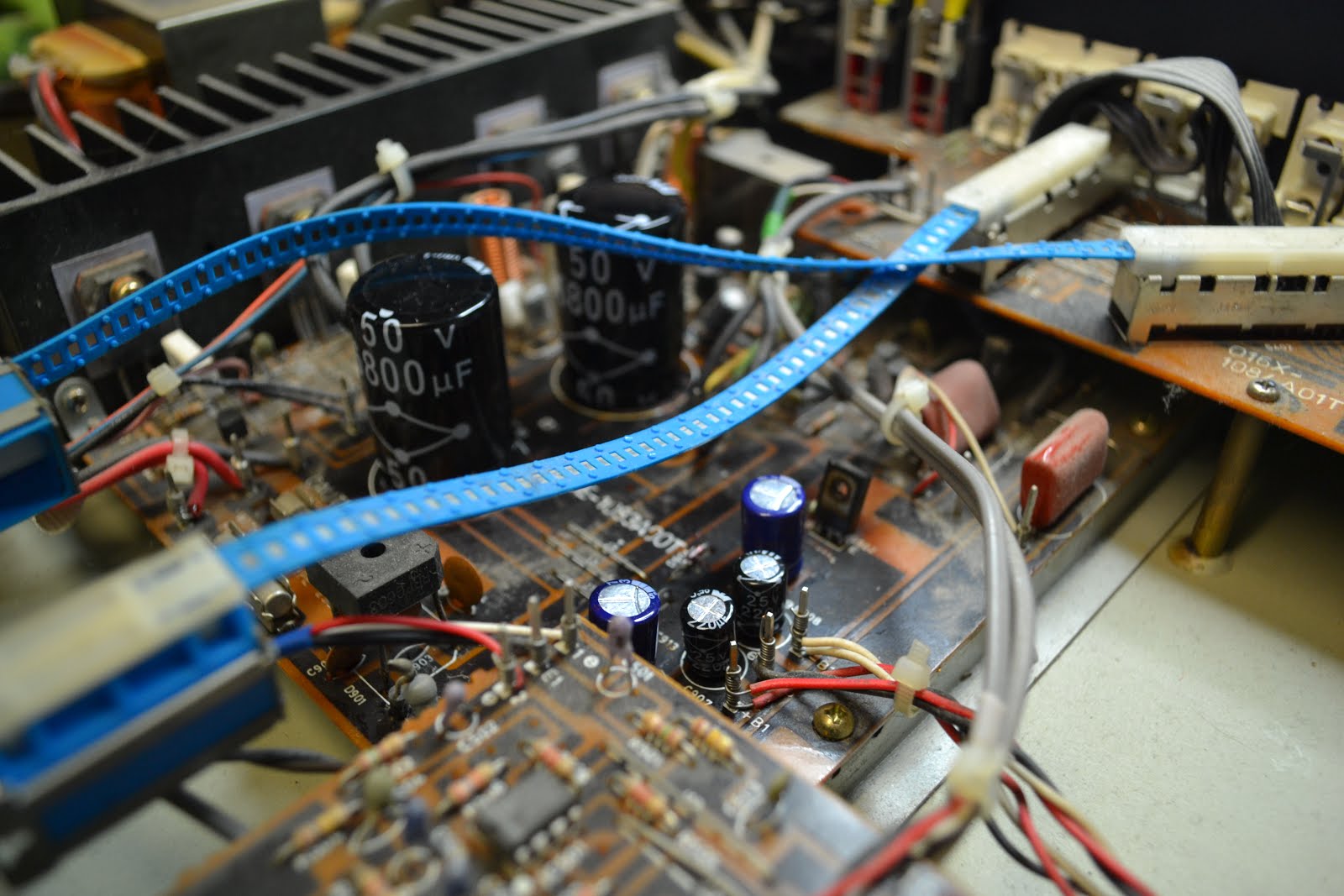
I check the outputs from the power supply with my multimeter... +5, -12 and +12.. +12 is varying between about 10.5 to 12.5, which may be acceptable. I switch to the 'scope and check the +5V again....

Woah! That's awful - 40V pk-pk of 50Hz crap riding on the output !


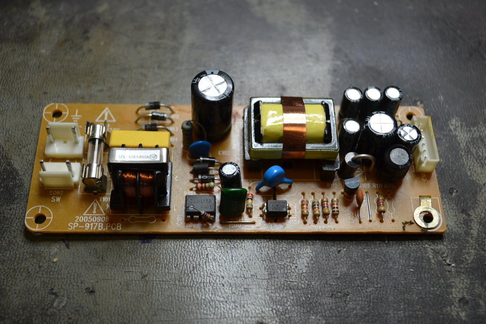
The power supply is removed, and a blanket change of all the electrolytic capacitors is performed, to ensure reliability.


The power supply is replaced, and on powering up, the disc spins up rapidly, and then reports "No Disc" ... hmmm ...


The laser pick up is given a gentle clean with some window cleaner (Don't use IPA on any CD or DVD, it damages the coating on the lens), and ....


Bingo, the test pattern DVD fires right up!


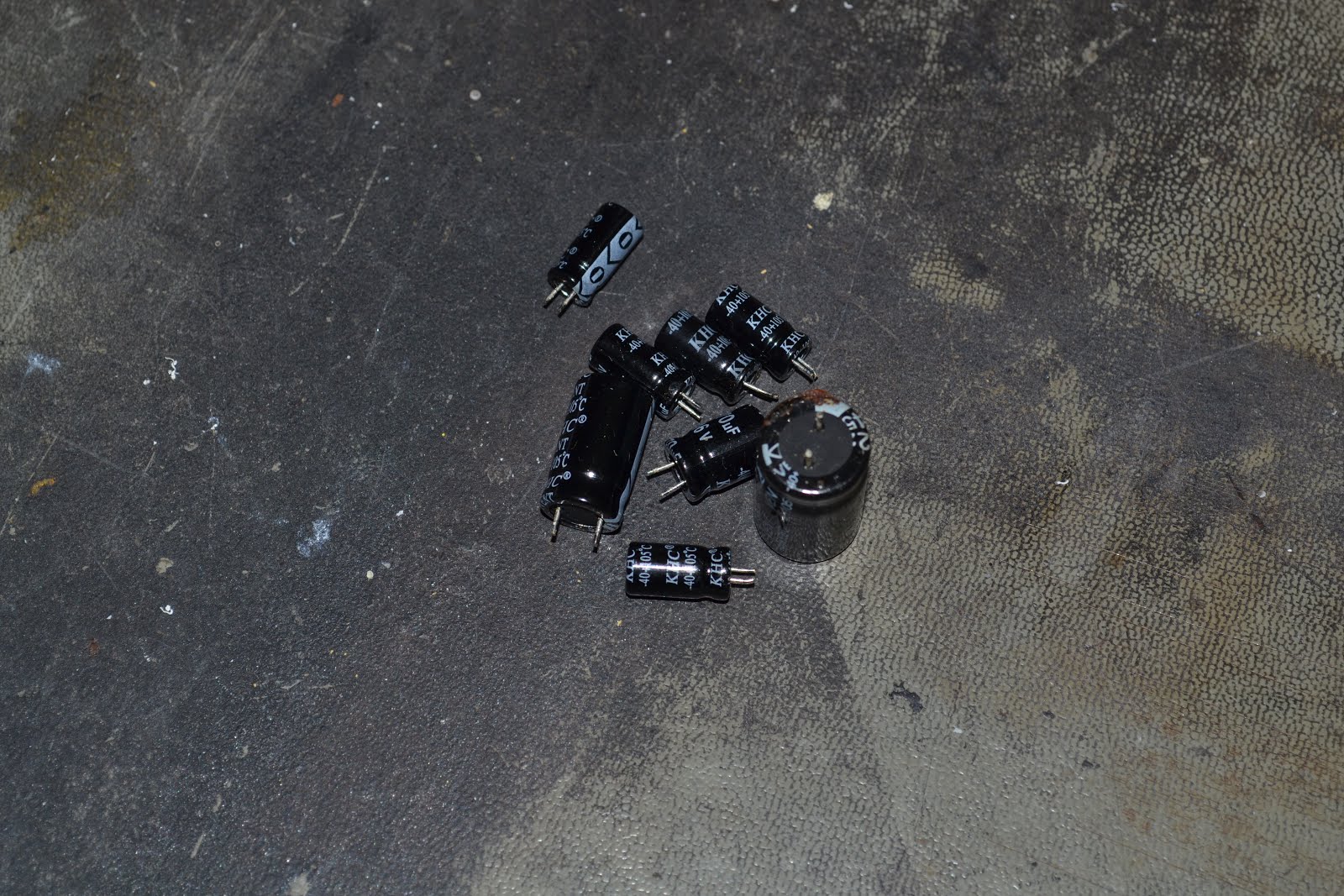
The guilty parties....

The sticking front tray is resolved by relieving the front a touch with a file... I suspect it's got distorted by the shelf above it in the rack for all those years...

Good, one fault fixed ... on with the next...


2 & 3 - Channels not working and crosstalk.

This is being caused by the mechanical switches failing on the front panel, there was always a bit of cross-talk (one channel seeming to "float" behind the video of another) as the switch does not provide any correct loading, or buffering between channels... 

What's needed is a proper video (and, of course audio) multiplexer.


I designed this a while ago in Eagle... thankfully Kicad reads eagle files :) KiCad, the gift that keeps giving :)

There are 8 audio and video inputs. 

Each video input is loaded by a 75 ohm resistor, and fed to two MAX4312ESE multiplexing ICs. One outputs the video to a UHF modulator, and one outputs the video to a 625/405 line standards converter. So, under the control of my favourite flavour of microcontroller, the ATMEGA328P, any of the video sources can be sent to either 625 or 405 sources.

The select line of the video multiplexer also feeds two ADG1408Y multiplexers, which switch the audio through to the relevant output device in the same manner. There's a 5532 buffer on the audio output, as there's none in the audio mux, unlike the video mux.

The audio mux requires a negative supply rail, and this is supplied from the microcontroller. A continuous squarewave is output on pin 5 of the micro, is floated by C9, and rectified by the double diode D1 (BAT54S) to provide a "-5V" supply, in reality it's more like -4V. 

The micro is controlled by a front panel , which has two push buttons, and a small OLED display.

A PCB was created... not modelled as it was Eagle, but Kicad has a go at it!

When Kicad imports an Eagle creation, it doesn't seem to cope with the ground plane or component models, but you get the idea... 


... anyway, the real thing turns up from PCBWay.

... and duly stuffed. I'll clean that flux up later ;)
The front panel was also designed. Simple.
and again, built up... not quite so simple though, as my new display has the power and ground pins reversed from the one I modelled :(


... so a minor bodge is deployed...


The software is very straight-forward. It acts conditionally on the actions of the select switches on the front panel to increment the channel address selected, and update the display. I used the U8glib library this time out, as it's got some nice fonts, and is quick, if a bit bulky.

The software can be downloaded from my git. https://github.com/andydoswell/video-rack

It will be noted that the hardware supports 8 inputs, and two outputs, but the software doesn't support that many, as I don't need them all! It's a simple task to enable more, if you wish.


Nice font...


So, back to the rack.


Out with the old...


Tidy up the RF wiring a bit. The black box in the bottom is the Aurora 405 line standards converter. The loop of co-ax you can see is a stub filter, as the output from the aurora is very harmonically rich, and the filter eliminates aome of the patterning caused by the harmonics effecting the UHF. What I really need is a low pass filter .... one day.


The UHF modulator (modified to run on DC, see here) is once again disassembled, so I can adjust the channel and sound carrier spacing via two buttons on the front panel. I've just soldered some wires on the existing switches, and made them available to the front panel.


The Cyclone media player, and HDMI converter are mounted on the shelf, and the multiplexer PCB behind that.


The power supply is a salvage 12V 5A supply. This feeds the multiplexer, and the aurora. It also feeds the modulator via a 42 ohm resistor (to give about 8V) , and an eBay 5V buck regulator, which feeds the Cyclone and HDMI converter.


The front panel is marked out...


... and the holes chewed out with my teeth. I do wish my metalwork was better, anyway, it's only for my own consumption!


And it's all wired up ... what a rat's nest!


The back's fitted, and it's all powered up and tested - No cross talk, all the inputs work - oh bliss!


Now, there's a rake of telly's here need fixing ....

Sunday 10 May 2020

IC tester - 555 4013 4066 and Quad op-amp.

Sometimes you just need a small test jig to test something quickly.

I built this up for quickly testing 555 timers, 4013 dual flip-flops, 4066 analogue switches and almost any quad op-amp a few years ago, I thought I'd share it here...


The 555 timers is set up as an astable. It's output blinks D2 at about 4 Hz. These pulses are used to test all the other chips, so a working 555 must always be inserted into the board.
To test the 4013, the clock pulses enter the Clock input of the first flip-flop at pin 3, Feeding the notQ output on pin 2 back to the data pin 5, results is the frequency being divided by 2. This is shown on D3. These f/2 pulses are then sent to the second flip-flop, which is configured in the same manner, the resultant output is displayed on D1, and is f/4.

In testing the 4066 switch, the pulses are fed to the switch input of all 4 quad switches. The inputs and outputs can be reversed, by reversing the polarity of the input and output between 5V. The practical upshot is the one set of LEDs should flash in time with the pulses from the 55. Flicking the switch, reverses the in's and out's, and the other set of LED will flash.

The op-amp is set up as a comparator, and all LEDs flash in time with pulses from the 555, although slightly dimmer than the other LEDs.

Here it is in action.

Wednesday 6 May 2020

"Linn" Hercules II power supply

The continuing story of the LP12 .... saints preserve us ...

This is an aftermarket thing (remember kids, Linn ownership is all about upgrades, right?), made to put two speeds on your Linn LP12, without all that tedious belt pulley swapping business...


Look familiar?


It's almost identical to a Valhalla, except it has some logic to switch between speeds like an Axis, and has two oscillators, and an analogue switch stuck before the pulse shaping, to change between the two oscillators.... oh and the print doesn't fall off when you touch it with an iron...

Anyway , this is my good friend Colin's, he's done the caps (and done a tidy job too), and it's still no good...

A quick check of the two crystal oscillators show they're both working, and so are the dividers. The output frequencies are 50Hz for 33RPM, and 67.5Hz for 45RPM. Both are present at the 4066 switch, and make it on through the pulse shaper , and are all fine at the output on pin 14 of U2 (again, sound familiar???) Everything goes pear shaped on the output driver at pin 8 though ....

Changing out U2 (an LM324 , instead of the LM2902 in a Linn supply) provides a cure.

Another Linny happy.... until the next upgrade....

Surface mount component storage tip.

If, like me, you're always making circuits up or repairing stuff, and minimum ordering quantities are always more than you need, you'll end up with more parts than you need.

With through hole components, it's not so much of an issue. Some of those compartmentalised boxes, and a few hours sorting out the parts makes an easy storage solution. Not so much with tiny SMD components. The parts are sometimes not fully marked, especially MLC capacitors, so it's best to keep them in their respective bags, or write the value on the tape. Even so it's all a bit unweildy.

I'm a big fan of these Chinese sample books.


They're about A5 in size, and great for storing a reasonable amount of stock in a small space.


No amount of trawling the internet reveals a supplier :(

So, after a bit of thought, and I order some of these Photo albums for very little money from eBay.

(looks like they're out of stock now... but the seller seems good, arriving promptly and well packaged)


Compact in size...


Lots of 6"x 4" (15.24cm x 10.16cm) pouches, that I can put my parts in, and label each pouch with a sharpie.


Excellent. Put an Index on the first page, and you'll easily find your parts!


Tuesday 21 April 2020

Dual PA5030 Integrated amplifier faults and fixes.

The famous George rang...

"Got this amplifier with a crackle... can you have a look?"

Yeah ... why not.


It's a Dual PA5030, a good quality hifi amp from around 1988.

Off with the lid, and a few issues are immediately apparent....


... leaking capacitors ...


... so they're evicted, the board cleaned up with some IPA, and the caps replaced with some nice new ones ...


Thankfully Dual provided us with a nice access panel on the bottom, making repair a breeze...


Switches and pots are duly clean ed up, the bias set, and the amp put on test. After a few minutes, the bias is checked, all is not well. The left channel's bias is moving about. It's set again, and something's obviously wrong. A low rumble is apparent in the left hand channel. Out with some freezer-spray-on- the-cheap. Spraying the Left hand output transistors restores operation. Damn. They're obsolete...

At this point I'm gifted another identical Dual amp with a fault! The output transistors are swapped out of this amp, and set up again. The fault remains....

Some head-scratching and a quick perusal of the manual is required...


The voltage on the emittor of Q617, a 2SB631 is wobbling about as the amp warms up. Replacement provides a cure.

The amp is a really impressive performer. The moving-coil input is a touch noisy, but looking at it's topology, not surprising. It's better than my Rotel. MM is very quiet, as is everything else.

Another saved from landfill!

Sunday 19 April 2020

Garrard Zero 100 from Hero to Zero (and back again) - Arm re-wire.

After successfully overhauling the mechanics of the Zero 100, I carted it in the lounge for a proper test.

All good ... a couple of LP's in and it loses the left channel. It comes back again.

Sunday morning, bacon sandwich. Beatles Rubber Soul. I return from the kitchen, coffee and sandwich in hand, and sit on the sofa, listening to the Beatles....

Funny, didn't think I had the mono press of this....

... and I don't.

Damn. Arm wiring.


Now I'm one of those odd people who actually enjoy arm wiring, but this could be a little daunting.
A quick google search chucks up loads of people who say it can be done, but it's very difficult neigh on impossible etc etc etc .....

Good, I like a challenge.

Cartridge Slide out first, and put it to one side, so we don't damage it.

Undo the gimbal housing screw and slide the gimbal housing down the arm and put that somewhere safe.


As there was no doubt in my mind that the wiring was at fault, I just cut it off ...


Slacken the arm bearing off, this will allow extraction of the arm.


OK so far ....


Removal of two screws allow the separation of the arm tube from the bearing support. There's a small grub screw at an angle, losen this to remove the plastic insulation "top hat" which the wiring passes through. I didn't do this at this time, and broke the wiring, not that that mattered.


I spent a few minutes looking at this, trying to work out how to get the headshell pivot apart.


Get a piece of blu-tak, and stick it over the pivot...


... and pull. Bingo, the small silver cover pops out, and reveals a small black plastic nut. Undo this, and don't lose the washer underneath it.


... And there's the wiring :)


The headshell is then removed, and four lengths of Litz wire prepared. Always allow for much more than you think you'll need. It easier to make it shorter ;)


A piece of teflon wire is used to pull the new new wire through the arm tube.


Out with the old ...


In with the new.


This is the angled grub screw I talked about earlier. Loosen this to remove that white plastic insulating "top hat".


Pass the new wiring through the insulator, and refit. The bearing support can now be re-attached to the arm tube.


My teflon wire is once again employed to pull the wiring through the centre of the gimbal.


Refit the arm, and nip the bearing up just enough to remove any play.


Refit the cartridge slide, with three wires diconnected, and, using a multimeter, identify each conductor. I use a coloured sharpie to mark each one.


and finally trim the leads, and solder them to the output connector.

The Beatles are now back in stereo (which is a pity tbh, the mono mix is far superior.)


Feet up, Sunday afternoon listening to The Blossoms.


Now, what about that plinth?