Translate

Tuesday, 10 March 2015

The MK87 Dreadnaught capacitor reformer - an explanation.

A terrific young lady called Elise has emailed me regarding my capacitor reformer. She'd like some more details on it's function, and, perhaps more importantly ... it's name.

WARNING. Do NOT try this at home. This project calls for some high voltages. It will floor you or kill you if you come into contact with it. It will not warn you, blow a fuse, nor pull your safety trip. It may not give you a second chance. RESPECT IT'S AUTHORITY.

Reforming capacitors carries the risk of explosion.

I will not, under any circumstances, accept any liability if you decide to re-create this project for yourself.

Now we've got that out of the way....

It's not a pretty looking thing. It's had many iterations, hence the state of the box. It used to have a 1uA meter movement (with adjustable shunts), but that suffered so many accidents, the needle ended up shaped like a banana, and eventually the meter went open circuit, due to a major overload. At this point I grafted in a digital meter, salvaged from scrap equipment. It directly reads 0- 999.9 uA, and is powered from a separate power supply (a redundant mobile phone charger)


The front panel also has the terminals for the capacitor under test, and a discharge switch.

On the side is mounted a selector switch, which switches in varying values of current limiting resistor. Nice labelling , eh?

The main power is supplied from a variable transformer (variac) which is built into by bench supply. It's variable from 0-350 VAC.

The sensible option would be to power the unit from a dedicated, isolated multi-tap transformer, but I don't have one...

It's wired up like this: -


So, what is this "reformation" anyway?

Well, when we're servicing or restoring a piece of ageing electronics, the electrolytic capacitors may have begun to lose their polarity. It's a chemical thing. My daughter would know. Anyway, the practical upshot is the capacitor will draw current if woken abruptly from it's slumber. (This even applied to "NOS" capacitors, even if they've never been used)

Say we have a 200uF 450V smoothing capacitor, and it's drawing 10mA at 400V, It's really pretending to be a 40K resistor, and it's going to start to dissipate power (Power = Voltage x current = 400 x 0.010 = 4 watts), and not only that but it's probably not being much of a capacitor either.

This power is going to be dissipated as heat. Now 4 watts doesn't sound like a lot, but this is inside a sealed can (usually aluminium) full of electrolytic gunge and tin foil. Pressure starts to build up inside, the resistance gets lower, more current is drawn, more heat is generated, and the whole situation just gets worse until the can explodes, and showers the workshop in bits of tin foil, and acrid smoke. If you ever experience this, just open a window with your now trembling hands, and leave for 5 minutes to allow the smoke to clear!

What the reforming process does, is let the plates regain their "form" or polarity. We need to gently apply power, and raise the voltage to the capacitors full rated voltage over a period of time. I usually do this for a period of a few hours, sometimes overnight.

So, having made our reformer, how do we use it?

Firstly we need to set our maximum voltage. Move the selector switch round to 0 ohms, and measure the voltage at the output terminals. Don't connect your capacitor as yet. Adjust the variac to give the required voltage (I usually use the rated voltage less 10% to allow for any variations in mains voltages).

Now switch off the supply and hit the discharge switch for 1 min. This will discharge C1. You can now connect the capacitor to be reformed to the terminals. Select the 12 megohm position, switch the discharge switch off, and switch the supply back on. The meter should show a few uA as the capacitor charges. Now decrease the resistor until the cap is drawing approximately 100uA and leave it there. Pop back in an hour or so, and the meter should have dropped again. Reduce the resistance again, and the meter will once again rise.

Repeat the above process until no improvement is made. Take your time. If the can is isolated, feel it to see if it's getting warm. It shouldn't. If it is, increase the resistance and just wait. Once the electrolytic has reformed, remove the supply, and hit the discharge switch. Wait for the capacitor to discharge.

What sort of leakage can we expect from an old electrolytic?

Good question. It depends on the value of capacitance; bigger values leak more. And voltage rating; Higher voltages *tend* to leak more. This is where experience is key. If your 22uF, 400V capacitor is drawing 1mA, forget it. If it's drawing 400uA it may be OK. If it's drawing 200uA or less, put  it back in the kit and switch on!

Modern capacitors have very low leakage values. Not so with the ancient stuff I deal with, but even 60 year old electrolytics that haven't seen power in decades can be reformed successfully. It's not always the case though. Some are beyond redemption, and replacement is the only option.

I sometimes choose to monitor the voltage across the capacitor during reforming, but we need to be aware that our meter will have some resistance of it's own, and will effect the reading on the current meter (it will increase slightly) and will drop the voltage across our capacitor slightly (as it discharges through the resistance of our meter). A good quality digital meter will have an internal resistance of 10 megohms. A moving coil meter , like an AVO 8, will have a varying resistance of 20 Kilohms per volt. Keep this in mind.

I'm lucky enough to have a capacitance meter (for measuring the actual value in uF) and an E.S.R. (equivalent series resistance) meter, and I'm always amazed how some of these old devices shape up after a successful reforming.

Now, here's the warning bit again....

A variac is NOT isolated from the live or line of your mains. Use an isolation transformer for your safety. Reforming a high voltage (more than 50v) electrolytic capacitor poses a very real shock hazard. It may shock or kill you. 

Be safe. There's only one of you, and I need all the readers I can get!

Oh yes... the name....

It was a joke. It started out as the dreadnaught , got blown up, became the dreadnaught MKII, then after so many failures and improvements, I lost count...

Friday, 6 March 2015

"Stupid" - The simple smart charger for lead acid batteries.

Now my good friend "Curly" has a caravan. It's a great little thing, but has the most bizarre electrics I've ever seen in a caravan. It's got AC mains, and AC 12V.... AC???!!! When mains isn't available , I think the idea was a relay clicked over to supply the internal lights from a battery someplace, thus switching from AC to DC. This battery was long gone, and most of the wiring with it.

Matt wanted to add a leisure battery back in to the electrics so he could run his LED lights and telly etc, without having to have a mains hook-up, and when mains wasn't present to charge the battery.

I took a look at the bizarre circuitry, and rapidly worked out we were going to need some for of charge controller, or "smart" charger to do the job.

Then I thought again. We've already got a nice 10A 12V AC transformer, and an automotive relay in this bizarre set-up, so can we re-arrange this to provide us some sensible charging?

Measuring the off-load voltage of our transformer showed that, after rectification we were nearing 18V. Not good for trying to charge our leisure battery for any length of time, it will simply out gas and dry out. Nah.

Some form of charge controller? Yeah. A pulse-width modulated thing, with possible arduino control and a sensible FET was considered. Then I got to simplifying. What we needed was a window comparator.

Now a window comparator circuit usually uses two op-amps as comparators, one to turn the relay on to start charging our battery when the battery volts are low, and one to turn the relay off to stop charging our battery, once the battery voltage has risen to a charged state. Now there will be much debate about sensing battery temperature, and constant current, baulk and float charge amongst you at this point, but let's keep this simple.

So, I start thinking about our window comparator, on at around 11.5V and off by 14.3V ... seems reasonable, a voltage reference, some potential dividers, a dual op-amp, a driver transistor and we're away .... but is there a simpler way?

How about just using a potential divider on the base of our transistor to switch the relay, and not using any comparators... well, that would work, but the hysterisis between the two required voltages might not be good enough and cause the thing to oscillate. I try it out. It oscillates. OK, so how about simply two transistors and a couple of steering diodes? Yep, that works... but can it be simpler still?

Looking at the circuit for a while, how about using the spare contact on my relay to switch in the second pot, altering the value of my comparator? Yep!

It's ended up like this:-


Now, it's not the easiest of things to set up. I connected Pin 30 of the relay to pin 87A of the relay and powered that point with a variable power supply to first set the minimum voltage (11.5V) using R2, then the maximum voltage using R1. Vary the power supply to the unit to see at what voltage the relay clicks over. There is some interaction between the pots, so it will take a few goes at adjustment to get the unit to achieve repeatable results.

Issues.

Yes, it's simple. There are issues. If something fails, there's precious little to stop it boiling our battery dry. The voltage control does seem stable in use, however. If the battery does fail open circuit, or F1 blows, the unit will oscillate... but at least the buzzing will draw your attention to the fact the battery has failed! The charging voltage does not compensate for changes in temperature.

Don't try and use this on a sealed lead acid battery. Chances are if something does go wrong, the battery will not be able to vent quick enough. It could burst. I've seen SLA's that look like footballs because they have been abused. Don't do it. 

When charging lead acid batteries, hydrogen gas is given off. Do not charge any lead acid battery in a confined space, or worse, a sealed box. No naked lights. I've seen tops blown off batteries as something has ignited escaping hydrogen. It's not good. 

Univox SR-55 Analogue Drum machine repairs. Korg Mini-pops!

My very good friend, and confirmed member of the Taffia, has passed this in my direction.

"Just sort of humms, can you take a look?"

... of course I can.


Good grief, what a rats nest! Not a single integrated circuit! Discrete transistor logic. Simple power supply. A real treat to fathom out!

 Connecting to the workshop amplifier and switching on reveals not so much of a hum, as a scream. A little reminiscent of 1980's Casiotone PLL chord generators, only very loud. Listening carefully I can hear some very faint drum sounds though the noise. Given the age of the equipment (possibly early 70's) I was hoping for a simple power supply repair, but no, those 40 year old electrolytic's test superbly.


On the top of the unit is also the sequencer. It's job is to provide pulses, once per beat. It's a discrete shift register. The clock speed (and thus, tempo) is controlled via a pot on the front panel.

Each  pulse is sent to the switch board, which decides which pulses should go to which "instrument" when. It's a huge wiring nightmare. The rhythms are hard wired in this switch bank.


So our pulse has left the sequencer, been routed through the switch bank, and on to the diode matrix. This is used to turn each timed pulse into the instrument we hear. Each diode passes the pulse to a whole bunch of near resonant filters on the rear board. Each filter is tuned to a different frequency, and two are noise generators. One instrument can be several filters being triggered at once, each triggered by the pulse sent via it's own diode. All the filters are mixed together, buffered and output via a volume control. There's also a tone control, which is simply an adjustable high-cut filter. There's a start button, which stops and resets the sequencer, or starts it running.

It's a simply stunning piece of equipment. With any sort of equipment like this, it's important to take your time and work through it. It's won't be complicated. It may look like it, but there's no odd ICs, no firmware and no pre-programmed bits and bobs only the manufacturer knows how they work!

So, what's wrong with this one? One of the filters seems to be resonating all the time, and howling. After some time poking around with a scope, it transpires that there's an inductor open circuit in one of the filters, and is causing it to oscillate. I have no idea what value the inductor is , so it's un-wound and re-wound with new wire of the same gauge... all 1,400 turns! Replacing it and a leaky 2SC828 transistor near by, followed by a quick set up produces some improvement. Some instruments in some rhythms sound distinctly odd though... One diode in the matrix is short circuit... replacement restores operation ...


Now... where's the Jean Michel Jarre LP???!

Saturday, 14 February 2015

Fast Arduino GPS Datalogger.


STOP PRESS! This project is now revised and updated here, and will now create KML files, to open directly in google earth!

Now, my friend Julian and I have, for the past three years, been building a racing car. I've been lending a hand with the electrics and certain mechanical bits.

It's based on a 1971 Mini Clubman (by the name of Florence)

Here's Julian, fitting the door mirror.


After it's first season competing (with Julian at the wheel) , it's not disgraced itself at a few hillclimbs...


This video isn't mine, but this is Julian at the National Championship at Wiscombe Park late last year.

Anyway. Julian wants a bit more power, this has necessitated a new and bigger engine, and a new and bigger carburetor. In turn, the baulkhead had to be modified to accommodate the changes. Now the lovely dashboard we had created to house the instruments had to face some changes, and the large mechanical speedo had to go (when you're racing, you're not looking at how fast you're going!)

We looked for a small speedo that would suit our requirements, but I mooted the idea of a digital speedo, collecting it's data from a GPS receiver... I have previously used U-blox receivers and chipsets commercially, so I ordered one from the lovely people at Hobby Components here.


Excellent. Provides updates at up to 5 times per second.

Now, this coupled to an Arduino pro-mini, and a nice OLED display would provide a nice speedo...

The display is a 128x64 SDD1306 OLED display, and was purchased from eBay.


Then I got to thinking ... what if I could log some data to an SD card as well... might provide some interesting data for when the car is racing. So I ordered an SD card reader at the same time ...


eBay is once again our friend!


Now first things first, we need to configure our GPS receiver. This is done by hooking up the receiver board to our PC (I used the same FTDI converter I use to program the Pro-mini boards).

Go and get yourself a copy of uCenter from the U Blox website here.

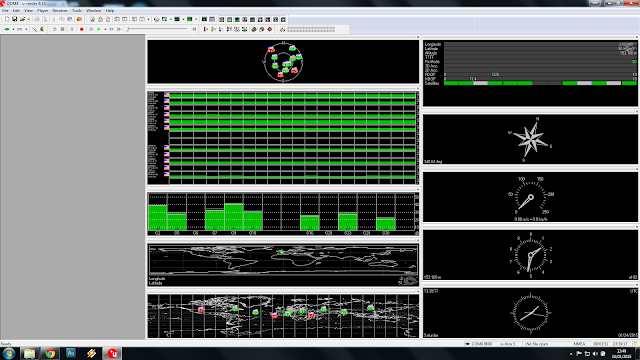
Now when the software opens, you will need to tell it which com port and baud rate the receiver is on. Click on the receiver tab, and select the com port. Try 9600 for the baud rate, if you see no data, try another speed. Soon enough you should see some data from the receiver.


Amazing, isn't it!

Now click View and Messages View. Maximise the messages window.

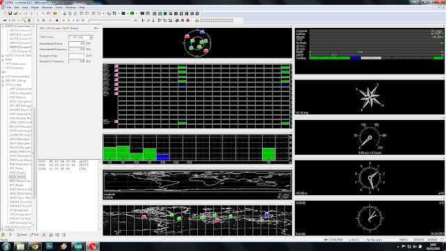
Now scroll down to UBX and click it to expand the tree. Click on CFG . Now click on RATES and change the Measurement Period to 200mS.

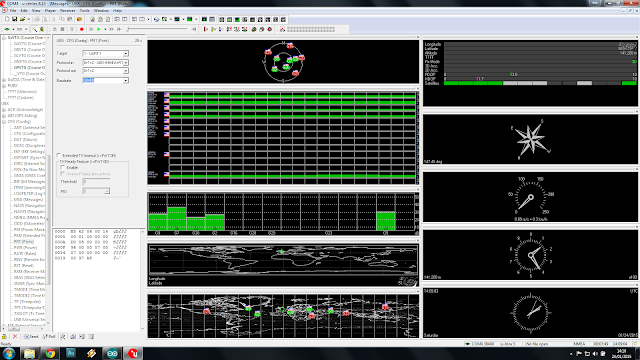
Now expand the PORTS section, and change the baudrate to 57600. Once you do this, uCenter will lose communications with the receiver module. Go to Receiver, and re-set the baudrate to 57600.


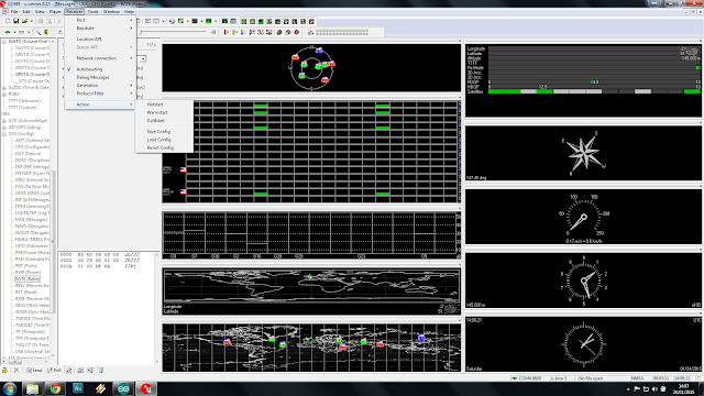
Now click on Receiver again, selection Action and click Save Config.


You can now disconnect the receiver from the PC.

Now, a word about power. The uBlox receiver is happy at 3.3 or 5v, The Pro-mini I've got is good at 3.3v or 5v, the display works great on 3.3v or 5v... the SD Card reader, whilst it has a pin marked 5v, is only happy with 3.3v on it's data and clock pins. The 5v is purely to power the on-board 3.3v regulator. Now, we can either run everything from 5v and use a level converter between the arduino and the SD card reader (stupid) , or we can use the 3.3v from the card reader's on board reg to drive everything else (a really good idea!)

So, from the car our 12v is dropped to 5v using an ordinary 7805 voltage regulator, this is then supplied to the SD Card reader. The 3.3V pin on the card reader then supplies power to the arduino, the GPS receiver and the display.

SDA on the display is connected to A4, SDC to A5. The SD card interface is connected to pins 4 (CS), 11 (MOSI), 12 (MISO) & 13 (SCK).

A toggle switch is connected between pin 9 and ground. The toggle switch is used to switch on and off the logging feature.

The GPS receiver's TX pin is simply coupled to the hardware RX pin on the arduino, but not until we've uploaded the software!

Now there is an excellent library to control the display from Adafruit, but it is very memory intensive, and somewhat slow. This caused difficulty in writing to the SD card in time.

After spending a while surfing, I happened upon a lightweight library at http://blog.oscarliang.net/arduino-oled-display-library/ which is perfect, although it's not designed for this display. There's a requirement to enable the on-board inverter in our sketch.

We'll also need the most excellent TinyGPSPlus library from https://github.com/mikalhart/TinyGPSPlus

The SD card will need to be formatted on your Windows PC as FAT32. Open notepad and save a blank file as gps.txt to the card.

Here's the schematic:-

You will notice there's a zener diode before the 7805, this to clamp any nasties that might be present on our 12V supply from the vehicle (usually on cranking). Any value between 18 and 32 volts will do. 

 Lashed up for testing...


 7805 power supply.

Will it all fit in the box?


Of course ;)


Painted black to match the dash.

Not many satellites being received on the bench!

But a few in the window!

The receiver is actually very sensitive, although initial lock may take a few minutes, once recent data is stored in the receiver's non-volatile memory, warm starts are very quick indeed.


Out for a quick test run, and logged some data....

 It's pretty easy to import the txt file into google maps, and get some useful data...


Here, individual data points are shown, each showing the speed at that point.


Anyway, here's the sketch....


/*
Fast GPS data logger.
(c) 14th February 2015 A.G.Doswell

Released to all and sundry under GNU License.

The sketch uses a U-Blox 6M GPS satellite module connected to the hardware serial interface, 
a 128x64 SDD1306 OLED display module connected as an I2C device to pins A4 (SDA)& A5 (SCL) and an SD card interface 
connected to pins 4 (CS), 11 (MOSI), 12 (MISO) & 13 (SCK) The arduino used is a Nano with 3.3v ATMEGA328P.
Warning - Many SD card interfaces are not 5V. 
There's a toggle switch which connects pin 9 to GND for Record.
Data is written to the card an impressive 4 times per second, in real-time. 

The OzOled library is not quite "right" for this application, but works, and is lightweight and fast enough. Thanks Oscar!
It is available here : http://blog.oscarliang.net/arduino-oled-display-library/
TinyGPSPlus is available here :https://github.com/mikalhart/TinyGPSPlus

*/

#include <SPI.h>
#include <Wire.h>
#include <OzOLED.h>
#include <TinyGPS++.h>
#include <SD.h>

static const uint32_t GPSBaud = 57600;
int SatVal;                        // Number of satellites locked
int Speed;                         // Speed in MPH
char SpeedA [4];                   // Speed as char
TinyGPSPlus gps;                   // Feed gps data to TinySGPSPlus
File myFile;                       // Start SD
int speedDigit;                    // Number of digits in Speedo display 
boolean card;                      // Is there a card present?
boolean rec = false;               // Is the record switch low? (false = high)
int recPin = 9;                    // Record pin (Pull low to record data) 

void setup()   {                

  Serial.begin(GPSBaud);           // Start GPS serial comms
  pinMode (recPin, INPUT_PULLUP);  // recPin as input and pulled high
  OzOled.init();                   // initialze SDD1306 OLED display
  OzOled.sendCommand(0x8d);        // Set displays inbuilt inverter on
  OzOled.sendCommand(0x14);          
  OzOled.setBrightness(0xFF);      // ... and brightness to max
  OzOled.clearDisplay();           // Clear the screen
  OzOled.setNormalDisplay();       // Set display to Normal mode
  pinMode(10, OUTPUT);             // CS for SD card, wether it likes it, or not.
  OzOled.clearDisplay();
  
  
  if (!SD.begin(4)) {              //Check SD card is present
      OzOled.printString("SD card fail    ",0,7);
      card = false;  
      }
      else {
      OzOled.printString("SD card OK      ",0,7);
      card = true;
      }
  
  OzOled.printString("Sats:",0,0);  // Set up display
  OzOled.printString("Speed:",0,1);
  OzOled.printString("MPH",7,6);
}

void loop() {
    while (Serial.available() > 0) //While GPS message received
    if (gps.encode(Serial.read()))
      displayInfo();
}

void displayInfo() {               // Display the data
  SatVal = int(gps.satellites.value());
  Speed = int(gps.speed.mph());
  itoa (Speed,SpeedA,10);
  OzOled.printNumber ((long)SatVal,6,0);
  OzOled.printBigNumber (SpeedA, 7,1);
  speedDigit = strlen(SpeedA);    // get length of Speed , and delete left behind zero if req'd
  if (speedDigit == 1) OzOled.printBigNumber(" ",10,1);
  if (digitalRead(recPin) == HIGH && card == true) { //If the record switch is high and the card is OK, write card data
    rec = true;
    OzOled.printString("SD card OK REC",0,7);
  }
  if (digitalRead(recPin) == LOW && card == true) {
    rec = false;
    OzOled.printString("SD card OK    ",0,7);
  }
  
  if (card==true && rec==true) {
    writeInfo(); //write the data to the SD card
  }
  smartDelay(200);

}

// This custom version of delay() ensures that the gps object
// is being "fed".
static void smartDelay(unsigned long ms)
{
  unsigned long start = millis();
  do 
  {
    while (Serial.available())
      gps.encode(Serial.read());
  } while (millis() - start < ms);
}

void writeInfo() { //Write the data to the SD card Date,Time,Lat,Long,Spped (MPH) and number of satellites locked
  
  myFile = SD.open("gps.txt", FILE_WRITE);
  if (myFile) {
    myFile.print(gps.date.month());
    myFile.print(F("/"));
    myFile.print(gps.date.day());
    myFile.print(F("/"));
    myFile.print(gps.date.year());
    myFile.print(F(","));
    if (gps.time.hour() < 10) myFile.print(F("0"));
    myFile.print(gps.time.hour());
    myFile.print(F(":"));
    if (gps.time.minute() < 10) myFile.print(F("0"));
    myFile.print(gps.time.minute());
    myFile.print(F(":"));
    if (gps.time.second() < 10) myFile.print(F("0"));
    myFile.print(gps.time.second());
    myFile.print(F(","));
    myFile.print(gps.location.lat(), 6);
    myFile.print(F(","));
    myFile.print(gps.location.lng(), 6);
    myFile.print(F(","));
    myFile.print(gps.speed.mph(),1);
    myFile.print(F(","));
    myFile.println(gps.satellites.value());
 // close the file:
    myFile.close();
  }
}

Saturday, 24 January 2015

Ekco U353 Basket Case repaired!

There's a lovely chap at work called Terry, who likes to restore old radios and record players. He arrived with this old Ecko U353 in bits in a box. "It's got cut wires and labels and has been got at. Would you like it?" Why not ...


 Wires cut. Looks like someone was going to change the mains smoothing capacitor.
 UL84 getter looks bad.
Most of the white lettering from the scale has gone...
... but on the whole the chassis looks reasonable.


The mains smoothing cap is not original, has been disconnected and is dated Feb '65. It has poor ESR....


.. so each of it's 3 sections is given a few hours on the ole' MK87 Dreadnaught capacitor reformer.....


 .... meanwhile the sad looking UL84 is tested on the AVO two-panel valve tester...

A sad 1.5 mA per Volt. Minimum for a new valve is 9 mA per Volt. No good at all....


Thankfully, we have a NOS replacement. Just look at the difference in the gettering (that's the shiny bit at the top). The new valve is on the left. The gettering is bright and has a nice sharp edge. The blacker the gettering is, the better. This new valve reads 15mA per Volt on the AVO!


Stamped on the chassis is a date ... 1st Sept ...19 ?? 1957 perhaps? Seems a bit early for this receiver...


There were many leaking and cracked Hunts capacitors to be changed, along with some suspect TCC electrolytics. The cathode bypass capacitor for the UL84 was short-circuit. That's probably why the valve was worn out.


 Remembering how there was a small decoupling capacitor in the U319 VHF tuner, which caused issues, I removed the cover to this unit (a much easier job that the U319!!!)
But the decoupling caps are Eire types, and all read in very good condition...


So, after leaving the mains smoother on the reformer with all 3 sections in parallel, the leakage had dropped to a very low 50uA!  ESR was good too, so it was re-installed and connected up. So all in all, 1 valve and 9 capacitors, and we're ready to go! Connect to the safety mains isolation transformer, switch on ....


... and after a few minutes warm up time, the DM70 indicator tube lights, and the set performs well...


In common with most mains sets of the period, the metal chassis is connected straight to one side of our AC line (in normal practice, the neutral)... this is referred to as a "live chassis" (even if it is neutral) , which mean the shafts for the controls are also "live". Now, until a set of insulating knobs can be found, this set can only be safely operated though an isolation transformer.


I did locate a nice shiny set of plastic knobs at a dealer locally. Whilst the knobs are plastic, the shiny coating must be metallic, as they conduct very well! These will NOT be safe!


Anyways, here's some good-looking chap to explain the set to you!

Wednesday, 14 January 2015

Hello!

I'd like to say a big "Hello" to Nicu from Romania, who's taken the pond pump controller and added a DHT11 to it to make a weather station.

You can read more here:

http://nicuflorica.blogspot.ro/2015/01/ceas-rtc-cu-ds1307-si-date-mediu-cu.html

Sunday, 11 January 2015

Sony KV1320 UB MKI restoration.

This has to be the shortest restoration ever. I normally like a bit of a fight from my restorations! A few juicy faults, but not this one! Testament to the quality of late 60's Japanese Engineering.

Now back in the day, set manufacturers had to pay a license fee to Telefunken to use the PAL system, rumoured to be about £30 a set. Sony got around this by decoding the colour signal in a manner which didn't infringe Telefunken's patents. Sony used a modified NTSC decoder, which had an additional delay line, and the colour was repeated from the previously decoded line, reducing the colour resolution, but on such a small screen this isn't noticeable. Any problems with phase could be corrected with the provided hue control, which PAL receivers didn't have, nor need.

Most of these sets died due to being worn out. It is very rare to find one with a decent CRT in, so I wasn't hoping for much, and anyways I paid little money for it, and it's a KV-1320 MKI, a very early one, as several revisions were made.

Being an early model, it has a 3AT2 EHT rectifier valve, and has the CRT heaters permanently connected and warm (not good for CRT longevity!) , regardless of the mains switch position.

This one arrived dead. No tube heaters, nothing.


Opening the mains plug... and the fuse is open circuit!


Replacing that and great pictures!!


 A quick tweak to the frame height and centering


Sit down, and watch telly! A sticker on the chassis show the manufacturing date as June 1969! Fantastic tube which these pictures really don't do justice to.


This sticker is intriguing. Most sets in the UK of this vintage had "live" chassis working, that is one side of the chassis tied to the neutral of the supply, and this has a warning sticker to that effect, but the set doesn't have this! It's a fully isolated design!