It looked as if it had been safely stored in a lake for the last 40 years.
It's a fairly straight-forward silicon amp, dating from ~1973. It uses 4 NPN 2SD180 output transistors, capacitively coupled to the speakers.
This unit had obviously seen a couple of repairs in the long-distant past. The first thing I noticed was the mains fuse, which looked like it belonged in a 1960's Morris-Minor rather than the mains input of this amp!
The mains input filtering cap, C28, was looking in a sorry state, so was snipped out, pending replacement, and mains gently applied via the variac. The power supply was obviously heavily loaded by something, as the voltage across C25 didn't rise as expected, and there was some excessive current draw from the mains. The HT feed wire was disconnected, and the voltage rose to an acceptable level, without the current draw. My immediate thoughts went to the output transistors, our 4 2SD180's , but these tested OK. I started to check the caps in the output stage, and every single one read high ESR, low capacity, leaky or a combination of all three! A blanket re-cap saw no real improvement of current draw when the supply was reconnected. Time to measure some voltages... With the mains set low, to give us an HT of ~5V, bias was obviously miles out, with two of our output transistors (Q2 & Q3) hard to rail. Tracing back showed either Q3 or Q5 were hard on, for no apparent reason... R5 had also risen in value to 1 Megohm or so. Q3 and 5 were removed and tested OK on the transistor tester, and found to read fine for gain and leakage. R5 was replaced. Powering on again showed no improvement. More voltage measurements again hinted that either Q3 or Q5 were the guilty party. Static testing of caps, resistors and transistors proved fruitless. Q3 and Q5 are 2SD317's.... and are so obsolete. Noah himself had discarded his stock (of two, obviously!) Looking at the spec showed an old favorite of mine, the BC547 may well do in that position, although it has a slightly less Vce of 50V as opposed to 70V for the 2SC317. I knew that it would never see more than 50V in this position, so I fitted two, and was rewarded with audio, albeit the output stage was still drawing too much current. Setting up the bias to the output stage (60mA) cooled things somewhat , and I left the amp on test for a while...
All was well, and the bias stable :)
All that remained to do was to recap the phono pre-amp board, a quick clean up and send it on it's way. The output capacitors seemed to read OK, and there's very little in the way of DC on the speaker terminals. The main smoothing cap also seems OK... After all that testing I suspect it had reformed itself, without resorting to the Dreadnaught capacitor reformer.
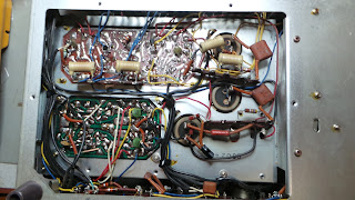
Top down...
 A mixture of construction, some tag-strip , but mostly PCB.
The finished article...
... and the guilty parties!
Nice selection of in's and out's... Note Tape HD, now that's not High Definition, oh no, that's Tape HeaD! It feeds the phono stage without the RIAA equalisation.
How does it sound? Phono preamp is a bit noisy. Best described as "of it's time" , but a nice piece of earlyish transistor hifi nonetheless.


