Translate

Showing posts with label Hifi. Show all posts

Sunday 22 November 2020

Strathclyde STD 305D Display fault

Remember the Strathclyde STD 305D I built a supply for here? Well, it ran for a while then the display started to play up .... 

It stopped indicating the correct speed. Ugh.


I got it back into the workshop, and poked around the board. 

The vacuum fluorescent display is driven by a long obsolete counter, a Plessey ZN1040. The good news is, it's actually counting. The bad news is that's all it does. The way it indicates RPM is it counts some pulses derived from the motor's tachometer , and a reset pulse comes along and resets the count. The display is then updated on reset, so 33 pulses per "reset" indicates 33 RPM on the display ... A prod round with the 'scope shows the reset pulse is missing. The pulse is generated from a Plessey ZN1034 precision timer IC, again long since obsolete. Damn. 


It's a bit like a posh 555 IC.. It's simply configured as a bistable. Replacements appear to be available on eBay, but are of questionable parentage. (You can't tell me that when this thing went obsolete in the early 80's, China had massive stocks of them).

We need to find another solution. 


This is a quick sketch of the relevant bit of the STD305D's schematic. 

As shown here, it's the Q output that feeds the reset pin of the counter. The complimentary output (not Q) of the ZN1035 timer is also feeding something, so we'll need to implement that also ..


The power supply available is 5V, so that's easy. How about an ATTINY85 ? Perfect. Two pins connected for both outputs, Q and not Q. Should be easy enough, and be easy to fit. Good, a plan. 

The program is simple enough ... 

#include <avr/io.h>
int timing = 1000;
void setup() {
  // PB 3 and 4 to output
  DDRB |= (1 << PB3);
  DDRB |= (1 << PB4);
}
void loop()
{
  //set PB3 , unset PB4
  PORTB = 0b001000;
  delay (timing);
  // set PB4, unset PB3
  PORTB = 0b010000;
  delay (timing);
}

I've used direct port manipulation to minimise the overlap between Q and not Q. digitalWrite takes longer to change the state of the port. I don't know whether that would be an issue in this application, but it's best practice. We can tweak the timing variable to suit.

The ATTINY85 is loaded into an adaptor and programmed using my ISP programmer


As power consumption isn't an issue, the micro is set to run at 16MHZ internal clock. 


The ATTINY85 is pressed into service, and produces odd results. The reset line still isn't resetting the ZN1040 counter. Checking through, I connect it directly to the reset line of the ZN1040 ... not a good idea, as this instantly kills the output pin on the TINY. :(

Liberating the ZN1040 pin from the board, the pin on the IC measures a few ohms to ground. Not only is our ZN1034 dead, but so is the ZN1040.... What's common here? Ugh , the +5V rail. 

I measure the 5V rail ... it's 5.1V , close enough.... hang on 5.2 .... 5.3 ... it ends up at 6V , the regulator on the power supply board is shot. It's a simple enough Zener diode and transistor affair... I sack it off, remove the BD239 pass transistor, and fit a 7805 on a heatsink. It's all a bit too late for our poor ZN1034 and 1040 though. 


So what to do? Obviously remove both IC's. Feed the pulses from the tacho into an arduino, calculate the speed, and output it over the existing discreet transistor drive circuitry to the display. Works for me. 

Studying the datasheet for the ZN1040 , gives us all the info we need... 


OK, so this is shown for LED displays, but the principle will be identical. Four lines switch on the supply to select which digit MSD (Most significant) to LSD (Least significant), only three are connected in our application ... We'll need to multiplex these, and the actual segment drives (A-G) need to be pulled low to illuminate the display. 


First up, is go get our arduino to read the pulses from the tacho. 

They should be arriving at pin 22...


... and, sure enough there's a nice negative going pulse train arriving, and it varies with the speed control. Great. 

We'll drop these pulses into INT0 on our arduino, and trigger an interrupt on a falling edge.


A quick piece of code is conjured up to read RPM and output over the serial interface. It's uncalibrated at present, but is near enough , reading 33, 45 and 78 RPMish...
Excellent, we can return to calibration later (the turntable is currently upside down with no platter on it).

Now to deal with driving the existing display. The ZN7040 is capable of muliplexing a 4 digit display. In this application only three digits are used. A quick bit of reverse engineering shows those digits are the 3 most significant digits. These are coupled to  our arduino on pins A1- A3 and set to digital outputs. Each of these pins feeds a grid, and taking this high allows the display to function.


Arduino pins 3 to 9 are connected to the segments drives for A through to G. These are used to individually control each segment's anode. Pulling the pin low, switches on the anode, and illuminates the segment. 

Bingo, a muliplexed display. Now to couple the two parts together...


And finally to reassemble and calibrate ...


Nice!


I will NOT be beaten by mere machinery!!

The software is available as usual from my github.

And another saved from landfill, these really are a stunning deck. 

Saturday 27 June 2020

Yamaha KX-580 fail...

It's the last of the famous George's kit to look at ...


It's a mint condition KX-580 with a nasty noise on the left hand channel.

When I say mint, I mean mint... it looks like it's never seen a cassette in it's life.


Sadly I rapidly trace the fault ... it looks like an open circuit head ...


... and sure enough it is ...


Game over. It's a special low inductance GX-37 head , and utterly unobtainium. I hate being beaten, but sometimes that's just the way it is....

Copland CSA-14 repairs

Jon what'sapped me ....

"Got a Copland here, previous owner accidentally dropped a bare wire across the speaker outputs... Care to take a look?"

He also sent a picture ...


Ah ... the magic smoke has escaped..

So, the thing is duly opened, and examined. 

It's quite obvious the unit has been modified by a previous owner. Caps replaced with "audiophool" grade parts. The speaker protection relay bridged out, because, you know, sound quality. Led hanging on the end of two bits of plumbers solder...

The quality of workmanship left a lot to be desired. Where some caps had been replaced, the leads hadn't been cropped off fully, and just bent under the board. The caps are of the wrong pitch, and don't sit snugly against the board... and one was fitted back to front, and had vented it's anger...

Cap in the wrong way!


... I mean ... what ?!?!
oh, and the fuse fairy has been in and liberated the fuse for the -42V rail to the right channel...

On the plus side, there's a pair of possibly the finest E88CC's ever made lurking in there, the Mullard CV2492.
OK, out with the output stage, which is unsurprisingly short circuit... both NPN and PNP transistors. The bias thermal compensation transistor is also OK, unlike the BD139 and BD140 in the speaker protection circuit, which I expect caught the brunt as they attempted to open the bypassed relay!
So we need a 2SA1302 and a 2SC3281... obsolete in 2000. But a reputable supplier has it listed, excellent. The two transistors are duly ordered along with a few replacement caps.

They duly turn up, and are fitted... but I can't set the bias correctly. The 2SA1302 is drawing far too much current. I check and check and check everything. Finally I swap the transistors out of the left channel, and everything is fine. I then google 2SA1302 ... oh dear. The world is full of fakes. My reputable supplier is contacted, and after an investigation, they remove the fakes from sale, and issue me with a refund. Reputation upheld!

Consulting the datasheet, I reckon an On-Semi 2SA1943OTU and 2SC5200OTU will fit the bill nicely. They're ordered from an official On-Semiconductor dealer. I'm not risking this again...

New transistors fit, bias correctly, and there's no difference I can measure (or hear) between the left and right channels. Why should there be? It's not a valve!

It's not a bad thing to work on, but for some reason, known only to Copland, the PCB is single sided, but has through-plated holes, just to make removal of a faulty part that little bit more tricky. The Metcal SP440 de-soldering tool worked a treat though.

It's given a LONG soak test, and is pronounced fit. 
Jon, it's done.... "Yeah, that Goldmund is playing up on one channel" ... this fills me with dread ... more later!

Later - other than a crap DC offset pot, the Goldmund was nothing serious, except I'd nicked a trace on the fragile front panel PCB, disabling an output LED, which meant a few hours work stripping it all down again! 

Thursday 4 June 2020

Goldmund Mimesis 3 Amplifier repairs.


Jon messaged me.

"How's my Goldmund amp looking?"

erm ...

"What Goldmund amp?"

"The heavy 1U thing.."

"Nope, I've not got it Jon ... "

anyway, after a bit of head-scratching, it turns out Colin's got it... it duly arrives..

It's dead and has a noisy left channel.

Modern looking thing, very neat in it's 1U case. Razor sharp heatsinks ...


Smart. It doesn't want to power up...

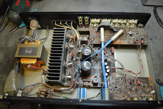
Off with the top cover, and ... well, I'm shocked...


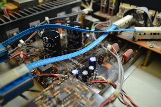
That's a lot of caps.... in a small space, and it's going to be hot in there...

Then I'm filled with nostalgia .... where have I seen these before ... ?


... oh yes ...

The old favorite Maplin 75W kit... a right of passage for any budding tech in the late 70's & 80's. A little bit of a challenge to get the thing to amplify rather than burst into oscillation, they weren't particularly stable, and required careful power supply considerations... but once running seemed bomb-proof.

Anyway, this appears to have had plenty of consideration to the power supply!


Under that black box in the middle there are 4 large toroidial transformers. A neat trick to get it all to fit in a 1U case.

Holding down both power buttons it's supposed to power up after a delay of a couple of mins... nah. Relays are clicking about, but nothing much doing.

 This is the soft start PCB, That 2.7K looks a bit cooked, but it reads fine. It's in close proximity to those caps...


After some disassembly, the caps are evicted and changed.  There are 2 x 4.7uF 100V and 2 x 22uF 63V


... and now the unit powers on fine :)


Running the unit at a humble 20 watts into a 8 ohm load, and those heatsinks are getting warm. The whole thing's rated to 200W, so 100W per channel, obviously not a constant tone though.

I have a word with Jon, and he wants all the caps changed to ensure longevity. That's a lot of work...

The parts are duly ordered and arrive next day.

First off 4x 15,000uF 63V...

Which, well, gives me a problem....

To remove the cap, we need to remove the PCB. To remove the PCB we need to remove the screw. To remove the screw we need to remove the cap.

It's schrodinger's capacitor...


It turns out it's not quite that bad, but still damned awkward.

There's some recessed screws which allows the front panel to come away...


But that still leaves the mounting bars covering a few of the 5 pins we need to desolder...

... right next to that LED too....


The trick is to desolder as much as you can from the back, and then get a long thin bit down between the cap and the board, where pins 1 and 5 are soldered to the print of that side, and work the cap out that way. It's not a nice job...

After several hours, and many words my mother wouldn't approve of, they're replaced...


There's a few smaller caps on the board to change too...

This on the left hand side of the power supply/front panel board, It's just tacked across a couple of tracks...


This cap, has had it's top damaged where it doesn't clear the Right hand amplifier's PCB...


... this cap has suffered the same fate, and it's rubbed it's value off... It's 4.7uF at 63V, and decouples the 24V rail...


To obviate the issue, I've laid the replacements on their side..


Next to re-cap the amplifiers themselves...  Access is at least easier this time... The thermal compound has dried out somewhat, and is cleaned off, ready for replacement once the amplifier is finished.

The print is not easy to work wth, it's double-sided, and has almost no thermal relief, so desoldering the caps where they meet the fat power rails is a real challenge, and clearing out the through holes a real pain.... it takes hours.


Halfway there ...


There are 4 caps on this back panel, which is also a right pain to get out, as the IEC socket must be carefully desoldered. 

Nothing is easy in here. The print is fairly fragile, and has no thermal relief


Finally it's all back together. Powered up, and after a few minutes to stabilise, the bias is checked. It needs no adjustment. I leave it on test for about an hour.... I'm in the lounge next door to the workshop... *Crack* and it goes quiet in the workshop ... 

Damn thing has blown 3 of the 4 supply fuses. Looking at the fuses, someone's been here before. They're not as spec'd in the manual. Two are T6.3A, and two are F8.8A (never seen 8.8A 20mm fuses in the wild before!) They are all supposed to be F6.3A. 

Cursory checks of the amp board shows our left channel to have a heavy load on it... sure enough one of the 2SJ49 FETs is now a short circuit. They're unobtainium (although equivalents are available, but this would require all the output FETs to be changed....) ... but guess who has a NOS spare !

It's fitted, the fuses replaced and powered up again. All is well. Bias is rock steady. I bet that's the cause of our noisy left channel too...

It's given a 12 hours soak test before it's pronounced fit.

All in all there's a lot of work gone into it... getting on for 50 hours... so hopefully it'll be good for another 30 years :)


The guilty parties.

Wednesday 6 May 2020

"Linn" Hercules II power supply

The continuing story of the LP12 .... saints preserve us ...

This is an aftermarket thing (remember kids, Linn ownership is all about upgrades, right?), made to put two speeds on your Linn LP12, without all that tedious belt pulley swapping business...


Look familiar?


It's almost identical to a Valhalla, except it has some logic to switch between speeds like an Axis, and has two oscillators, and an analogue switch stuck before the pulse shaping, to change between the two oscillators.... oh and the print doesn't fall off when you touch it with an iron...

Anyway , this is my good friend Colin's, he's done the caps (and done a tidy job too), and it's still no good...

A quick check of the two crystal oscillators show they're both working, and so are the dividers. The output frequencies are 50Hz for 33RPM, and 67.5Hz for 45RPM. Both are present at the 4066 switch, and make it on through the pulse shaper , and are all fine at the output on pin 14 of U2 (again, sound familiar???) Everything goes pear shaped on the output driver at pin 8 though ....

Changing out U2 (an LM324 , instead of the LM2902 in a Linn supply) provides a cure.

Another Linny happy.... until the next upgrade....

Tuesday 21 April 2020

Dual PA5030 Integrated amplifier faults and fixes.

The famous George rang...

"Got this amplifier with a crackle... can you have a look?"

Yeah ... why not.


It's a Dual PA5030, a good quality hifi amp from around 1988.

Off with the lid, and a few issues are immediately apparent....


... leaking capacitors ...


... so they're evicted, the board cleaned up with some IPA, and the caps replaced with some nice new ones ...


Thankfully Dual provided us with a nice access panel on the bottom, making repair a breeze...


Switches and pots are duly clean ed up, the bias set, and the amp put on test. After a few minutes, the bias is checked, all is not well. The left channel's bias is moving about. It's set again, and something's obviously wrong. A low rumble is apparent in the left hand channel. Out with some freezer-spray-on- the-cheap. Spraying the Left hand output transistors restores operation. Damn. They're obsolete...

At this point I'm gifted another identical Dual amp with a fault! The output transistors are swapped out of this amp, and set up again. The fault remains....

Some head-scratching and a quick perusal of the manual is required...


The voltage on the emittor of Q617, a 2SB631 is wobbling about as the amp warms up. Replacement provides a cure.

The amp is a really impressive performer. The moving-coil input is a touch noisy, but looking at it's topology, not surprising. It's better than my Rotel. MM is very quiet, as is everything else.

Another saved from landfill!

Sunday 19 April 2020

Garrard Zero 100 from Hero to Zero (and back again) - Arm re-wire.

After successfully overhauling the mechanics of the Zero 100, I carted it in the lounge for a proper test.

All good ... a couple of LP's in and it loses the left channel. It comes back again.

Sunday morning, bacon sandwich. Beatles Rubber Soul. I return from the kitchen, coffee and sandwich in hand, and sit on the sofa, listening to the Beatles....

Funny, didn't think I had the mono press of this....

... and I don't.

Damn. Arm wiring.


Now I'm one of those odd people who actually enjoy arm wiring, but this could be a little daunting.
A quick google search chucks up loads of people who say it can be done, but it's very difficult neigh on impossible etc etc etc .....

Good, I like a challenge.

Cartridge Slide out first, and put it to one side, so we don't damage it.

Undo the gimbal housing screw and slide the gimbal housing down the arm and put that somewhere safe.


As there was no doubt in my mind that the wiring was at fault, I just cut it off ...


Slacken the arm bearing off, this will allow extraction of the arm.


OK so far ....


Removal of two screws allow the separation of the arm tube from the bearing support. There's a small grub screw at an angle, losen this to remove the plastic insulation "top hat" which the wiring passes through. I didn't do this at this time, and broke the wiring, not that that mattered.


I spent a few minutes looking at this, trying to work out how to get the headshell pivot apart.


Get a piece of blu-tak, and stick it over the pivot...


... and pull. Bingo, the small silver cover pops out, and reveals a small black plastic nut. Undo this, and don't lose the washer underneath it.


... And there's the wiring :)


The headshell is then removed, and four lengths of Litz wire prepared. Always allow for much more than you think you'll need. It easier to make it shorter ;)


A piece of teflon wire is used to pull the new new wire through the arm tube.


Out with the old ...


In with the new.


This is the angled grub screw I talked about earlier. Loosen this to remove that white plastic insulating "top hat".


Pass the new wiring through the insulator, and refit. The bearing support can now be re-attached to the arm tube.


My teflon wire is once again employed to pull the wiring through the centre of the gimbal.


Refit the arm, and nip the bearing up just enough to remove any play.


Refit the cartridge slide, with three wires diconnected, and, using a multimeter, identify each conductor. I use a coloured sharpie to mark each one.


and finally trim the leads, and solder them to the output connector.

The Beatles are now back in stereo (which is a pity tbh, the mono mix is far superior.)


Feet up, Sunday afternoon listening to The Blossoms.


Now, what about that plinth?