Translate

Tuesday 21 December 2021

Building an Altair 8800 Clone.

Having had a bit of a clear out of the workshop recently, I found a very posh (and expensive at the time!) rack case. 

I need something to build into it. Let's re-create someone else's project for a change..

What about a MITS Altair 8800 clone? That would be exciting, and there's a ready-to-roll Arduino emulator available. It really is an extensive project, but using inexpensive hardware. Details can be found here.

So, parts are procured... An Arduino Due clone, a bunch of LEDs and switches.

The original clone project called for a bunch of buffer transistors to drive the LED's, as if they were all lit up, the maximum source current of the Due would be exceeded. I must say, the designer does like to run his LED's at a higher current.But who doesn't like some bright LED's? You could increase the current limiting resistors, and not bother with a buffer, but who doesn't like some bright LED's? The buffer board consists of a lot of transistors. Let's simplify this and use a few 74HCT541 non inverting buffer IC's. We've got more bits than we need.. you never know.. expansion or something!


A PCB is created, and sent for manufacture.. 


Now we're going to need a front panel made, and I used Front panel designer to re-create something a bit like the original. It's sent off to ATP Projects to make it reality. Files for the front panel, and buffer PCB can be found on my github page here.


Now, as well as the human/machine interface being handled by the front panel LEDs and switches, it also has a terminal interface. I dislike the idea of hooking this up to a modern computer, running some serial terminal. I'd rather it had an interface of it's own. Now various bits of video hardware are supported by the emulator. I like the idea of a composite output, emulating a old style terminal (I did look, briefly, at procuring an old VT52/100 compatible terminal... whoa, there's some money now!). I can make a serial terminal to output composite video easily enough using Arduino, and to send data from a PS2 keyboard, but there's already a polished, open source solution already out there, courtesy of Geoff's projects. It supports PAL and NTSC and VGA, and emulates a few different terminals. The gerbers are downloaded, and sent for manufacture.

The front panel arrives . It's superb. 


... as do the PCB's...


The buffer board is the first to be populated. 


The LED's are fitted to the front panel and held in place with a dab of adhesive. 


While this is drying, the Due clone is uploaded with the code. You'll need to install any missing libraries, and ensure the version of the SdFat library installed is 1.1.4, later versions throw the error 'File' has no member named 'getSFN'.

The front panel switches are added in...


... and the long, tedious job of wiring it all up...


... LEDs to the buffer ...


... buffer to the Due, with SD card adaptor used as a reader as per the instructions. I hope you like the "mother" board ðŸ˜†.


Switches connected...  Note the micro SD card adaptor is used to connect SD storage to the Due.


... and a quick test shows some fault finding is needed as a couple of the LED's aren't working, which is thankfully easily sorted. 

Next the video interface is built up, and programmed with Pickit 5 (Graham's design uses a 32 bit PIC microcontroller)


The MPLAB IDE faultlessly uploading the firmware.


In the interim period, I'd managed to get hold of a small black and white CRT monitor on Facebook Marketplace, for peanuts. I'd tested it, and it performed well with a test pattern from the video rack. Thanks Colin! 

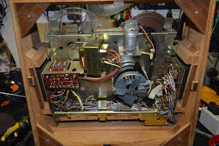
It's not got a makers name, but I'm thinking it may be a Hitachi or Shibiden. 

It's vintage and looks the part... 


Hooking the output from the PCB to the monitor and switching on produced less than encouraging results. If you look carefully, you can *just* make out some text in the top right of the tube ... and why is the line sync showing up white?? 


Reversing the video connection solved the issue. Serves me right for using the wrong type of socket! 


... and once a compatible keyboard is located, RX and TX pins shorted together to get an echo test to work ... 

Brilliant. Now to connect it to our Altairduino!


The RX & TX lines are connected to pins 18 & 19 of the Due, and the unit powered up. With a serial terminal opened via the USB port on the Due and my PC, the Stop and AUX1 switches are raised to put the unit into config mode, where the default serial terminal can be moved to pins 18 & 19. Don't forget to save as default! (If you do this without an SD card present, the default settings are saved to EEPROM within the Due. If you subsequently fit an SD card, the process will need to be repeated, as the default is then saved to the SD card. 

So far the machine has been running from 5V supplied by my bench supply. A simple power supply is built up on a piece of perfboard. It's a rectifier, some smoothing and a 7805 regulator. LEDs are added to the input and output, just because ... 


A suitable 6V transformer is mounted into the enclosure, along with the supply board, and connected up .. 

Mains will eventually be supplied via an IEC connector on the rear panel.


I want to replicate the Altair badge on the front of the machine, so I order a piece of thin aluminium, cut to the required dimensions by eBay seller Penninehardwaredirect. Just message them the required size, and they do the rest. A first class service. 

I spent a while searching for the right sort of font, and 256-bytes fits the bill.


It's flipped to mirror image and laser printed onto some glossy photopaper, and that is then ironed onto the aluminium strip, with the iron on the hottest setting. It's exactly the same procedure as making a toner transfer PCB.

Soak off the paper... 
... and give it a light coating of clear protective lacquer...


.. and stick it to the front panel with some contact adhesive. Smart.


A back panel is fabricated from aluminium to (my now) legendary high standards (ahem). It's not from this rack unit though, and this rack doesn't appear to have any means to attach a back panel....
So some doo-hickies are drawn up on CAD, and 3D printed....


... and pressed into service ... 

Nice ...


The back panel is secured into place, and I'm thinking it's finished. I was wrong. 


The keyboard interface isn't working. It was previously working fine. Doing a loop-though test, the terminal appears to be sending data, and that's confirmed with the oscilloscope.... Some head-scratching occurred... Also another weird thing was happening. Any traffic on the USB com port of the Due was being relayed to the terminal board via pins 18/19. The Due was erased and re-flashed. Same weirdness... It's also refusing to read the SD card... 

A replacement (genuine this time!) Due was ordered,  and some aspirin to cure the headache caused by the wiring, and this sorted the issue.


I also ordered an SD extender , and used this instead of the adaptor. I can conveniently locate the SD card reader on the exterior of the case now. 


Right... I'm off to see if I can complete Infocom's hitchhiker's guide to the galaxy!


Monday 20 December 2021

Someone's been here before .... The Sony TC-377.

Jason from the record shop called.

"A mate of mine has a Sony reel to reel that's not working, can you take a look?" 

Yeah ... why not.


It's a Sony TC-377, very nice. 

A quick test, and it refuses to go into play. A common issue, usually to do with sticky grease on the selector cam, worn or perished belts, or worn or perished idlers. Rewind and fast forward are in rude health, so that rules out a couple of the idlers straight away. 

Let's get it apart.

Remove all the knobs from the front panel, they should all just pull off, except the pause lever which unscrews clockwise. Remove the head cover, and unscrew the retaining pins. Now I've smelt a rat, they're lose. They're never lose. There are also five retaining screws on the front panel, or rather there should be. One is significant by it's absence. There's one that's easy to overlook... it's by the heads. 


The front panel then lifts away. 


Four screws remove the back panel. We won't need to be in here, but if you have no motor running, or it's just humming and not turning, the chances are that silver motor run capacitor as the top has thrown in the towel, and needs replacement. It's a dual value cap, one is for use on 60Hz supplies, the other, placed in parrallel for 50Hz. You only need to get one value to replace it, unless you intend to go globe-trotting with the thing... For 50Hz operation, you'll need 2.0uF , for 60Hz 1.5uF. 


OK, we need to remove the mode selector mechanism, which is a pain. First off remove the three screws circled in red, which will allow you to remove the heads in one piece, don't undo or losen any others!!!  There are three brass spacers behind, put them somewhere safe. Now remove the four screws circled in cyan. Note here than one of mine is chewed up ... hmmmm.

You can now extract the mechanism, unhooking the levels and wiggling off the take up belt from the capstan flywheel as you go...  

Now, I expect this mechanism to be covered in gold-coloured grease, that is doing the perfect impersonation of glue. Normal procedure is to clean it all of with IPA, diassembling as required, and re-lubricating with superlube or similar.. But this has already been done. Only one issue is the cam select lever has jumped behind it's slot. It's a quick fix... 
... but it's not the end of the story. There's a couple of brake pads missing in action, and the capstan drive idler lever is seized up, so the capstan never gets drive. The idler is secured to the lever with a circlip, so that's popped off and removed.
We can't disassemble the lever, as it's riveted together, so some heat is applied to the pivot with the soldering iron, and some penetrating oil gently worked into the pivot. Eventually it starts to move, and some spray grease is eased gently in to prevent re-occurrence. The lever should move freely, and spring back into position. 

There are a few other levers on this side of the mechanism which look like they are in need of some attention, so they're sorted out, and new brake pads fabricated and fitted. 

Finally the mechanism is reassembled and tested. 

The tape has some Christmas carols on, how appropriate.


And the case is reassembled. 

Another saved from landfill! 


Saturday 4 December 2021

Trevor's Tandberg TP41 and the mystery of the "Stabistor"

 Trevor called..

"Do you remember my Tanberg radio you repaired for me a while back?"

As it happens, I do... I fitted a new telescopic aerial, and cleaned up the controls a bit.

"It's howling, can you look?"

Yeah, why not...

Well, Trevor made a couple of attempts to get it round to me, each time thwarted by the radio, obviously feeling threatened by a trip to see Doz, putting itself right, and behaving again for days.

Eventually the fault was more or less ever-present. 


It's a Tandberg Portable 41, dating from around 1970, and just oozes Nordic quality.


I got the thing on the bench , and sure enough it's sat there ... making a sort of mooing noise, that varied in frequency with the volume control. 

Let's get the thing in bits... 


First off remove the two screws to the left and right of the handle.. 


Gently bend the handle out and remove it..


Unhook the aluminium side pieces from the bottom of the case, one each side... 


You can now remove the wooden "clamshell" from the chassis..

Remove the knobs.. 


You can now remove the top. You'll notice I removed the telescopic aerial too, there's a screw in the base, and, once removed, it just slides out of the top. I'm not sure it was necessary to do this. 


Remove the two handle retaining plates before they fall off.. 


(It's worth noting how they sit the the grooves in the top panel to aid reassembly later!) 


We can now get at the PCB, but access to the component side is difficult... 


So remove the speaker , and place it carefully to one side, you won't find another... 


Of course, once it was disassembled, the fault vanished....

Some googling occurred, and a schematic obtained. 

This website, had a very detailed description of the set, and suggested the "Stabistor" was at fault...


The what? Stabistor?

So, the schematic is consulted.... 


It's a weird looking thing, and, as suggested in the website, is very corroded.. It's shown on the schematic as an ST1,5, given the designator D501, but it's not some sort of diode. It's drawn as a battery, and that's sort of what it is... it's acting as a voltage stabiliser, feeding a stabilised 1.5V supply to the RF & IF stages. 

It doesn't look corroded here, as the green corrosion just fell away. It had sort of made it's way down the wire end, and had even corroded the PCB, which took quite a bit of cleaning up before it could be persuaded to take solder again.


"That's bound to be the fault" ... a big bag of red LED's is opened, and each one tested, until I find one with a sensible forward voltage drop, that I can use in place of the stabistor. It's tacked into the circuit, along with a 220uF capacitor to decouple it, and the radio is powered up .... no mooing! Excellent.

I put the radio back together again , and listen to it for the rest of the evening in the workshop.

The following morning , back in the workshop ... and the cow is back ! Damnit. 

If the quiescent current adjustment (R518 on the above schematic) is just barely touched, the fault can be *almost* cleared. The instablility is once again permanent. 

(As an aside, you may notice the audio output stage is a mix of silicon and germanium transistors) 

The audio input to the output stage is disconnected by lifting C506. The fault still persists, so it's in the output stage somewhere.... 

There's a few electrolytics in there ... C512 (1000uF) is the output coupling capacitor, C513 (1000uF) is some local supply smoothing. These appear to be in reasonable condition, but changing them clears the fault temporarily. It can be made to become unstable again by adjusting the quiescent current again. Voltages on the output pairs base's are unstable... There are only a few electrolytics in the whole set, so they are all swapped out. The fault vanishes once more. The quiescent current control can be rotated and no instability re-occurs .... The quiescent current is reset by measuring the current flowing into the collector of Q503, set for 5mA.

Here's our stabistor replacement LED glowing away. It provides about 1.45V, slightly less than the 1.5V of the original component, but it shouldn't ever fail, and performance doesn't seem affected.


The guilty parties ... and another saved from landfill !