Translate

Friday 27 August 2021

Sinclair ZX Spectrum repair

George rang... 

"Got a ZX Spectrum here that doesn't work. Care to have a quick look?"

Yeah... why not?

It duly arrives in the post. 

I have to be honest, and say I haven't so much as seen one since the 90's... and only fixed very few back then. 


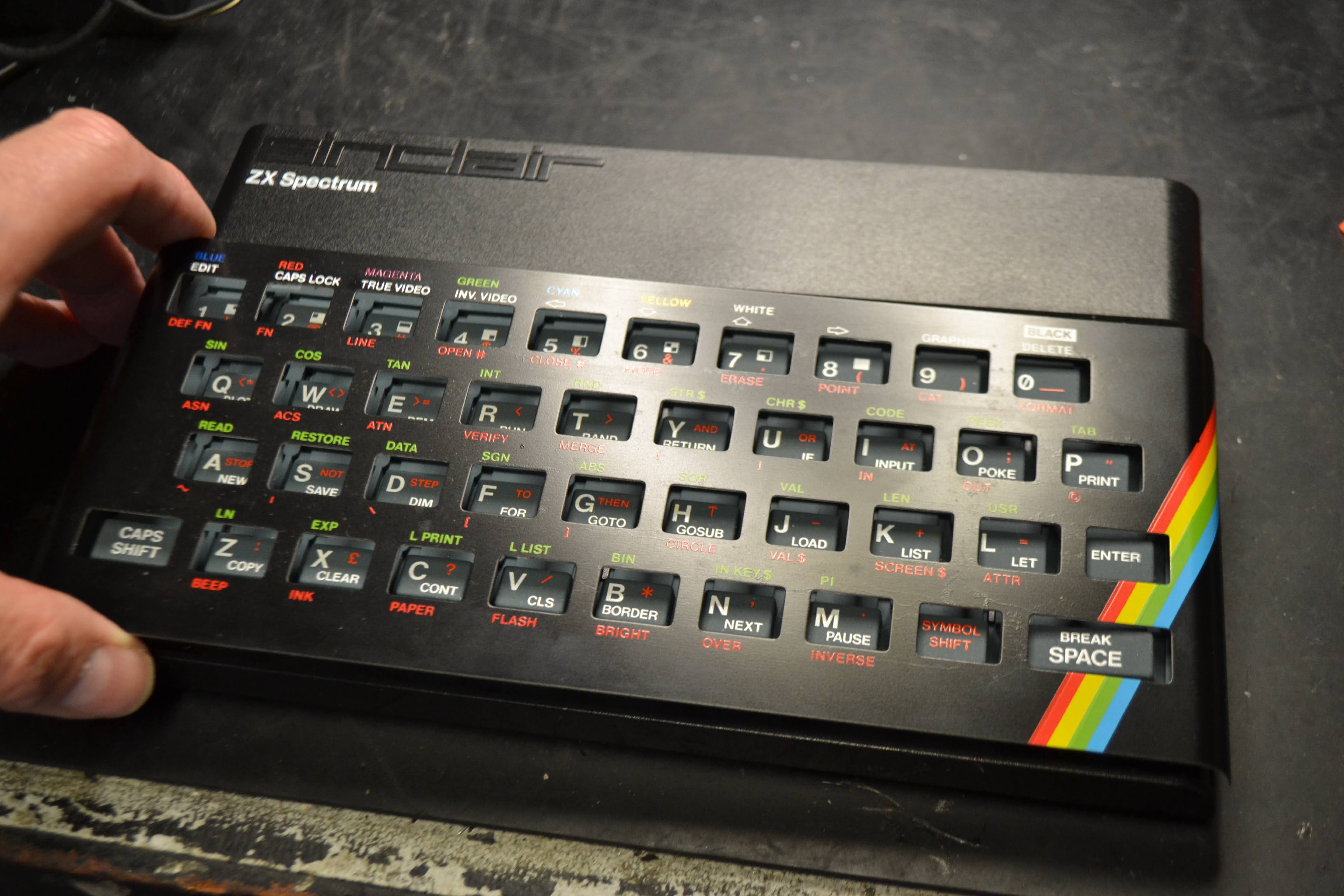
It's the earlier sort, with the rubber keyboard. 

The power supply is tested (Centre negative!) and it's output is around 14V DC off-load, so that's OK. The supply is put to one side, and the unit is powered up from the workshop supply. Something is loading the supply heavily.

Five screws in the bottom of the case gives us access to the PCB. 

Carefully remove the two keyboard ribbons, and remove the single screw in the middle of the board, to remove the PCB. 

This machine is fitted with a version 4 PCB, and the chips are all dated around 1984. 

Attention is focussed on the power supply. 

It consists of an LM340TS (7805) linear regulator, and a small self-oscillating supply, which provides + & - 12V, -5V (not at 20 amps!!) and a 12V "AC" rail


A few cursory checks, and it looks like our 7805 has failed, thankfully short circuit to ground, rather than short circuit from input to output... having ~14V on something that's expecting 5V can really ruin your day.


The heatsink and offending part are removed from the board (carefully, the double sided print is fragile) and a Traco TSR1-2450 switched mode IC fitted in it's place. This is pin-for-pin compatible with the 7805 it replaces, but barely gets warm to the touch, and requires no heatsink. 


The rest of the board is in really nice condition. The modulator's a bit rusty, but it's getting on! 


Powering up the unit, and we have life.. but just a black screen with a white boarder. No copyright message, no keyboard clicks... Removal of the socketed IC's, and a quick clean up with some servisol contact cleaner .. and we can try again.


Bingo, the familiar (C) 1982 Sinclair Research Ltd message appears on my (rather small) workshop test monitor!

The obligatory test programme is typed in ... 

... and it runs, but all is not quite right ... 

Keys 1 to 5 don't work. :( It'll need a new keyboard membrane. 

Never mind, we can at least play Manic Miner... 

So a .wav is obtained of Manic Miner, and loaded onto my aging MP3 player, and connected to the Spectrum's EAR socket... 

LOAD ""

The boarder changes colour as it's supposed to, but no amount of amplification persuades it to pick up the pilot tone, nor can I hear the tone through the speaker. My heart sinks at the thought of a faulty ULA ... 


The tape and sound interface all share a common pin on the ULA (28) ... audio comes in to our EAR socket, is loaded by R37, fed via R36 and C32, with a bit of filtration by C35. D13 Clamps the signal, and it's passed to pin 28 of the ULA. Also hanging on pin 28, is an output to the MIC socket for saving programs, and, via D9 & TR7 out to the speaker. Possible candidates for failure are R36 & C32 open circuit (unlikely), C35 & D13 short circuit. D9/TR7 and possibly even the speaker faulty, or, of course the EAR socket itself. The ULA could be faulty, and loading the whole thing down. So, we have key clicks, which shows that the speaker and TR7/D9 are working, and that the ULA is at least outputting something (whether it can input, is undecided at present.) and that it isn't being loaded down by a short circuit D13 or C35. We also can't hear the signal through the speaker, so that leaves us C32 or R36 open, a duff EAR socket, or a ULA that goes into a low-impedance situation when it's set to receive audio. What's the betting it's the socket ... after-all, that's the bit that had all the abuse in the 80's! 

After tracing the audio through the circuit, it's not the EAR socket! It is in fact, and open circuit C32! 
As an aside, it appear my 4B board differs from this circuit diagram, as TR7 is fed from the 12V rail, rather than 5V as shown. 


LOAD ""  


Bingo! 
Now onto the keyboard. Yesterday I ordered a replacement membrane from the fabulous  https://www.retroleum.co.uk/  . It arrived this morning. What fantastic service! Phil who owns the store also manufactures a replacement ULA, called a Nebula for sensible money, although stocks are short at the time of writing.

The kit comes well packed, with detailed instructions, and a plastic razor blade tool.

Changing the membrane is simplicity itself... 

Flip over the keyboard, and carefully bend the brass tags straight. Later computers apparently have the front plate stuck down with some double sided tape, which the plastic razor blade will assist in removing.


The plate can then be lifted off. Some wiggling and tweaking of the brass tags was required...


The old membrane can now be lifted out, and the new one slots right in. I have to say I'm now a bit worried, as the numbers 1 to 5 have a conductor in common... what happens if I've missed a broken connector, and the membrane's not at fault? I suppose I've just spent a few pounds for nothing...


Thankfully, my diagnosis of a faulty membrane was spot on..


Another saved from landfill!

Wednesday 11 August 2021

Sanyo TP1100 Turntable repair.

Colin rang...

"Got this Sanyo turntable here ... doesn't work, got a new Rega Carbon cartridge on it, but doesn't spin. Nice thing, heavy , all die-cast ... are you interested for £15?" 

Now, under normal circumstances, I would have taken Colin's arm off... but right at the moment, I'm planning a major workshop build, and if I bring anything else into the house, the current Mrs Doz is likely to serve divorce papers. I politely declined.

... time passed ...

Colin rang..

"Need a turntable for Fiona, sensible price.. have you got anything?"

"I haven't, but what about that Sanyo?"

"It doesn't work."

"No, but I'll see to that... "

So it arrives in top-secret, under the cover of darkness....


The turntable powers up OK, and moving the arm over should automatically start the platter. Nope, but the neon stroboscope lights up.... "The lights are on, but there's nobody home".

First off, remove the mat and platter, and place safely out of the way, then remove the screws from the edge of the blow-moulded bottom cover.

There's a DC controlled direct-drive servo motor, and some levers to automate the turntable. 

The simple DC controller is mounted to the impressive die-cast chassis, and is powered from a small transformer, well away from the arm end of the deck.
The turntable's power is controlled by two microswitches attached to a spring loaded lever at the base of the arm. 

The microswitch nearest us controls the power to the neon... The other switches the secondary from the transformer (about 20VAC) to the speed controller board. 


The neon works, but the motor doesn't, and a few checks prove the microswitch isn't working anymore. 

It's removed, and a replacement sourced. 

Unfortunately, the replacement is useless... It requires too much force to engage the switch. The spring on the lever is too weak, and with good reason, its triggered by a cam on the base of the arm... too much force here would be disastrous. 


OK, now a switch with low force is available, but not in that form-factor. Some head scratching ensues... The original (but broken) switch is refitted. The two yellow wires from the broken switch are shorted together, and tidied up. 


The transformer's feed from the LIVE side is disconnected and is now connected to the switched live side of the neon strobe... so when the neon's on, the transformer is connected, and it's output fed to the speed controller... 


... all is well. Almost. 

There's a *click* on the audio as the turntable starts up and stops. We'll have to live with that, until a suitable switch is obtained, anyway ...

Another saved from landfill! 

The turntable is tested with Nicky Thomas "Love of the common people"

Tuesday 3 August 2021

Dozcord.

Let's try something new... 

I've made a Discord server.

Pop in and say hello.


... why not?

Tuesday 27 July 2021

Dash-cam irritation avoidance circuit (How to use a sledgehammer to crack a nut). A guaranteed supply.

My dash-cam has a irritating issue. If I stop at the traffic lights, and switch the engine off in the car to save a little fuel, and hopefully reduce my environmental impact, when I restart the engine, sometimes (most times) the camera hangs up and stops recording. It's powered from a 12V to 5V USB adaptor plugged into the accessory socket. What's probably happening is the supply is momentarily dipping and the micro inside the camera is "browning" out, despite having an internal battery. No messing about with the camera's settings or firmware have solved this issue. 

What we need to do is make a little circuit that ensures the power supplied is OK. 

My idea is, if the main supply dips or even switches off completely, the supply is temporarily held up by a small LiPo cell for 3 minutes. After the that, power is removed, unless the 12V is restored within that time. This should be long enough if I'm sat in traffic, even if I've switched the accessory socket off. 

Here's the schematic:
12V arrives to one of those small buck converters (from eBay/Aliexpress etc) .. and is used to provide a 5.7V regulated supply via one half of D1 to supply the 5V for our camera and the ATTiny85 microcontroller. It's also feeding one of those small PSU boards for charging a LiPo cell & boosting it's output that I used in the Geiger counter project (albeit modified). This board is unmodified, and is adjusted to provide 5.2V output. 
Once the microcontroller has started up, it takes PB0 High, biases on Q1 via R2, and energises the relay. This connects the LiPo cell to the charger/boost controller. The 5.2V output is then connected to the other half of D1, which is currently reversed biased, and does nothing. The output from the 5.7V converter is monitored by the microcontroller PB1, via D2.
In the event of the 12V supply failing, PB1 will be pulled low by R3, as the 5.7V supply is removed, and a timer is started. 5V supply is now maintained, as the output from our 5.2V Lipo boost converter now feeds the 5V supply, as the second schottky diode in D1 is now forward biased. Once the 3 minute timer has elapsed, PB0 is taken low, which kills the LiPo supply by opening the relay, and, as there's no power supply anymore everything stays off, until the 12V supply is restored. 
R1, D4 and C3 form a reset delay circuit. C1& C2 provide some power supply filtration & decoupling. D3 prevents the back-EMF from the relay coil destroying Q1. 
The principal is the same as the circuit I used to write the mileage to the EEPROM on the Mini speedo project.

The code is simplicity itself, and is uploaded to an ATTINY85, set for a 1MHz internal clock.

# define OUTPUT_PIN 0
# define SUPPLY_OK 1
unsigned long timer;

void setup() {
  pinMode (OUTPUT_PIN, OUTPUT);
  pinMode (SUPPLY_OK, INPUT);
  digitalWrite (OUTPUT_PIN, HIGH);
}

void loop() {
  if (digitalRead (SUPPLY_OK)) {
    timer = millis ();
  }
  if (millis() > timer + 180000) {
    digitalWrite (OUTPUT_PIN, LOW);
  }
}

Possibly (!) far too complicated. I could simply use a high side drive FET circuit to drive the output, and use a simple RC time constant to drive the FET, but I suspect the actual parts cost would be about the same, and I don't have a suitable FET in the junque box!

Right, down to construction...

Having got a bunch of parts from the junque box, the circuit is constructed on a bit of perf-board.  

I added an LED across the 5V output, just so I could see what was going on during testing.


All mounted up in a *slightly* too big box, and I could have used a smaller relay (had the junque box provided one) . Input lead is connected to an accessory plug, and output via a USB socket. 


And finally put into the clutter box in the car, and connected up. It performs faultlessly ...


Which is a good job, because this is the state of the wiring on the old USB supply I'd just removed ðŸ˜¬

Sunday 4 July 2021

Aurex (Toshiba) SB-A10B

The ever-cheerful Matin's been badgering me to do a couple of amps for him, a beautiful Luxman R-1040, and an awful Aurex SB-A10B ... he's off on holiday, so dropped them off on his way past...


The label helpfully has the fault description "As they say in Brum, it woo gooo!" which roughly translated means it's doesn't work.

Fancying a quick win before tackling the enjoyable, but somewhat arduous task, of re-capping his Luxman, we'll have a quick look.

It's one of those small form factor separates, and quite well regarded (by those who don't have to fix them) Aurex was Toshiba's "posh" range of hifi.

Something's nagging me in the back of my mind, that last time I did one of these it didn't end well... 


The first challenge is to get the damn thing apart. Remove the Bass, Treble and Volume knobs, and every damn screw you can see... there are plenty. Don't forget the two recessed ones.


Now start wiggling the case around until frustration builds to an almost intolerable level. 


Eventually the top should "ease" forward. Not much room in there....

We need to get the bottom off now....

.. and at this point it's worth noting that the service manual tells lies. At no point does it mention that you need to remove this screw. Remove it. 

Now spend another 5 minutes wiggling the case like a demented fool, only to discover you can't until you remove the two plastic tubes that surrounded those two recessed screws from earlier.


... remove the two plastic tubes, take a deep breath and start wriggling the case like a Tory MP in front of a select committee, until it finally yields. 

You are now faced with a densely packed lump of electronics. Complete with surface mount resistors (in 1979!) ...


The mains fuse is located under a small plastic cover by the on-off switch. It's visibly blown, and looks to have failed with purpose.

It's a T1A fuse, and is duly replaced.


Voltage is gently increased on the variac, whilst monitoring the current, and it's very clear something is under a lot of load. 

Measuring the output transistors on the left channel, and all is well... measuring the right hand channel and the output transistors (2SB595 and 2SD525 respectively)  are short circuit, well bang goes my quick fix... and they're made from unobtainium (enter the whole of the internet saying they're still available on eBay, off you go and order them then, good luck if they're shot or fakes). Great. 

Some discussions are had with Martin, ruining an otherwise pleasant holiday no doubt, and I reckon an MJE15030 and MJE15031 will do as sunstitues, so some are ordered from a reputable supplier. I will not be beaten by mere machinery. 

I have, however, got an awful sinking feeling... 

... eventually the Luxman is finished (phew!) ... so it's back to this ... 


The heatsink and output transistors are removed as one piece... Both transistors are lose on the heatsink! No small wonder they failed.

The NPN device has been especially warm!

Look at the state of the insulator! We'll have a nice new one.

The MJE15030G and MJE13031G substitutes are pressed into service, after checking the driver transistors are undamaged, which they are...

Both channel's screws are locked into place with a dab of thread lock.

The unit is lashed up naked on the bench, and power is supplied gently via the variac ... after a few seconds the speaker protection relay clicks, indicating there's no DC on the speaker outputs.. Good.


The bias is set up as per the service manual, and speakers connected up... 


... and knock me down with a feather, it all works and sounds great! It's left on test for a while playing The Lasters by Fred Deakin. 

Now the fun and games shoehorning it all back into the case...


... and after much cussing and swearing ... 

... another saved from landfill!

Luxman R-1040 Repairs and restoration.

 Look at it..... 


...Just look at it...

What a thing of beauty. A joy to behold. 


It's a Luxman R-1040 receiver, dating from 1978.
I'm somewhat jealous. A quote from Hifi Engine "It has a genuine output of at least 40 watts continuous per channel into 8 ohms from 20Hz to 20,000Hz with no more than 0.05% total harmonic distortion." That's a very fine spec today, let alone 1978.

This one belongs to cheerful Martin, and has issues. It makes a noise like the tide going out when it's first switched on, some of the lamps have failed, the pots and switches are all scratchy, and Martin would like it re-capped. No mean feat. 

Right, let's crack on... 

There are 6 fittings, which look like they'd be perfectly at home on some Ikea furniture underneath. Remove them with the receiver on it's side, and simple slide the whole chassis out. Put the wooden cover somewhere out of the way, where the cat won't use it as a scratching post.
... it's almost as good looking on the inside as it is on the outside... look at all the space (are you listening Aurex!) 

Access is generally easy. We're going to need to remove the power amp board from the output transistors, and the volume control board to gain access to some of the caps thereon, but it's all very nice.
It appears a cap has let go in the past, as there's some debris... 


A quick look at the service manual and some nice Nichicon caps are on there way. (I would have gone with OE Nippon's, but the price!! I'm damned if I'll pay over £50+VAT each for some of them!) 

You've got to love the march of technology! The new cap on the left, which has a better specification than the old on the right...


The output transistor's heatsink is removed to facilitate change of capacitors, and the output transistors marked up, so they go back in the same order, and the old heatsink grease cleaned off and replaced with thermpath. 


There's a considerable number of caps in this unit, so it takes some number of evenings to complete.


Martin mentioned he wanted the dial lamps replaced, as one had failed... 

This necessitated removal of the front panel...  

.. and the dial glass. 


Despite the remaining dial lamp shining a white light, when it was disassembled, There were two green caps, which had faded / melted with the heat. The original illumination would have been green.


The white wire is disconnected from the power supply tag pin 10, and a 1N4007 diode and a 470uF capacitor are fitted to switch the supply to DC, so we can fit some appropriate LEDs easily...


... nice...


Bias is set for 45mA (after a minute or so's warm up), DC offset nulled out and the pots and switches cleaned.


And finally all buttoned up and tested.