"Dozman, the darts scoreboard's fallen off the wall and stopped working... Can you take a look?"
This is going to be easy ...
"Yeah, why not?"
It's a keypad entry thing, with two big 7-segment displays, that allows a person to accurately score a game of darts, regardless of how much beer has been consumed. It's powered by a USB-mini socket and matching wall-wart.
Removal of the back reveals a small PCB...
There's a micro controller, some form of display multiplexer, and the membrane connector.
And, rather oddly, something that proports to be a "Supercap" , but is only 0.047F 5.5V (47,000uF) - not really that super...
After examination of the USB socket, it's clearly damaged. The USB socket also has it's data pins conected to the microcontroller, presumably to facilitate easy programming at the factory. Connecting the 5V rail up to the workshop power supply proves all is well.
The USB plug is cut off the wall-wart, the polarity checked with a meter, and hard-wired to the PCB. A zip tie is used to provide some strain-relief.
Another saved from landfill!
... although some people obviously need to improve their aim!!
A while back the boss was having a big clear out of this basement, and, having been a fully signed up, Parker-wearing anorak of old, found a GE Superadio 3.
This was made for the US market only, but benefited from a sensitive FM & AM receiver, with an AM "Wide" mode.
In the US, AM channels range from 525KHz to 1705KHz, in 10KHz channels. This gives the station a maximum audio bandwidth of 5KHz, but I suspect many stations may have used more, hence the Superadio being equipped with "Wide" mode for improved audio quality.
In the UK (and EU) , we used 2 AM bands for broadcast , one Longwave (LW or GO in France) and Mediumwave (MW or PO in France). Eventually, after things were standardised throughout Europe, our channels were just 9KHz wide between 525 and 1605KHz (with one other allocation at 1611KHz for Vatican City). This allowed only 4.5KHz of audio, and often a narrower bandwidth of 3.5KHz was used to prevent "splatter" on adjacent channels.
The Superadio is connected up to a variac, and supplied with the required 115V. Nothing. Nada. It's taking no current from the supply. I connect my bench supply, set to 9V to the springs where the 6 D-calls normally reside, and there's a click from the speaker, but nothing more.
Measuring the resistance across the American mains plug shows it's open-circuit. Perhaps the 115V transformer was inadvertently connected to our UK 240V mains, and (rapidly) failed, perhaps damaging the radio circuitry itself before expiring.
Removing the tuning knob, and the bass, treble and volume knobs from the radio, and undoing the 6 screws holding on the back, allow the radio to be removed (not without some struggle) from the case.
The speaker wires are unsoldered, and the workshop speaker temporarily connected.
Getting some life back into the radio is simple, a quick squirt of contact cleaner on the switches and pots restores operation, at least from the bench power supply.
Let's investigate the mains. I'm hoping for a blown fuse, on a transformer which I can simply rewire the primary for 240V operation...
Once the screws to the tuning scale-frame/mechanism and plastic PCB frame are removed, desoldering
the AM radio aerial connector from the rear panel, sufficient access is gained to the underside, where the transformer exists...
It must be under that small fibre cover...
... hang on, what are those three wires that look to have been cut ... some sort of test jig used in production? Surely easier to have used a connector?
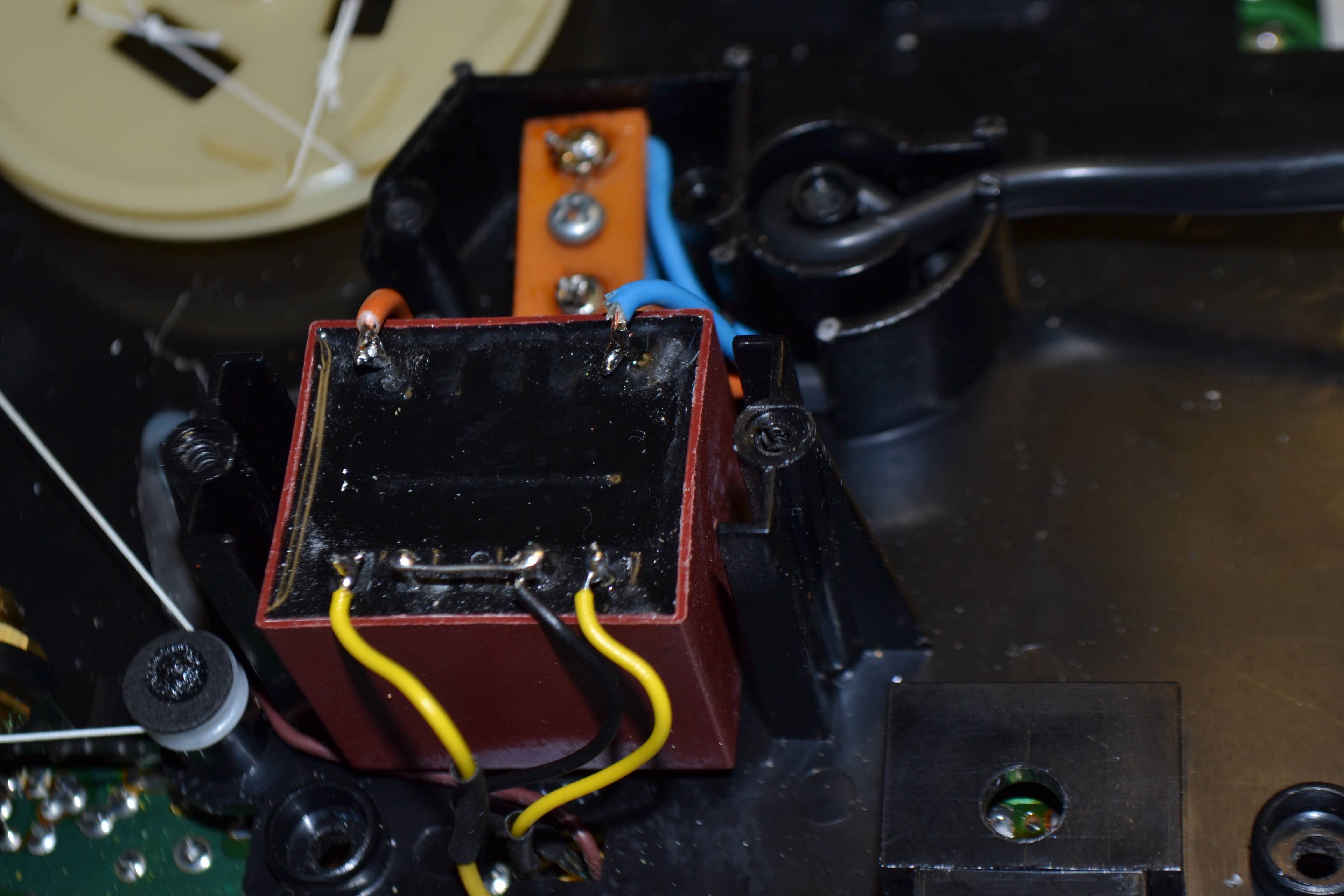
The small fibre cover is removed, and all becomes obvious. It's just the strain relief for the mains cable, and a small circuit board for the juction between the transformer primary, and the mains lead (and another mystery component, covered in heatshrink... read on). The transformer is absent without leave. The cover just protected the mains junction, and providing some strain relief for the mains lead. Perhaps the boss removed it to prevent damage if connected up here in the UK?
A small 2 x 6V transformer is ordered, and turns up the next day.
The circuit is very simple. It's just a transformer, and a full-wave rectifier. What bothers me is that mystery component, wrapped in heatshrink. It's connected between one side of the mains, and chassis ground of the radio.
A quick look at the schematic show's it's a 2.2M Ohm resistor. What's it purpose? It would leave the exposed metal battery terminal, as well as the ground terminals on the antenna connector referenced to mains, albeit via a large value resistor.
Am I happy about that? I make a post on the VRAT forum for knowledge.
Whilst awaiting a reply, I remove the american mains lead, as it's not double insulated. And fit a new lead. The original lead, obviously had a american two pin plug on it, and it hides away inside a small compartment in the cabinet when the radio is being used on batteries. Now there's no way a UK plug is going to fit inside that compartment, so I'm going to fit a male IEC connector, on a short bit of lead.
The new transformer is a PCB mounted type, as that's what I could get that would fit. It fits neatly in the hole, and I've superglued it in place, however, it needs some sort of bracket to hold it down.
When I started this repair, I had never used my 3D printer before, so this was first time I've designed something, or 3D printed anything.
A model is created in Fusion 3D. Sliced in Cura, and the results fed into the printer...
And 43 minutes later , it's done!
I have to say, I'm very pleased for a first attempt.
So the conjecture on VRAT is that the 2.2M resistor was probably there to assist signal coupling to ground, and is better and safer left out, as I suspected.
The new transformer has it's two secondary windings connected together, to form a centre tap, and connected up. I've tucked the 2.2M resistor out of the way, so if we ever fancy re-instating it, it's there. I take the opportunity to fit a wire-ended 250mA fuse underneath the junction PCB.
I must say I'm very pleased with the results.
An IEC plug is fitted, so the lead still fits in the rear compartment.
The electronics is tested and it's all working well.
The front speaker grille is removed by bending up the tabs...
... ugh. Years of filth! The speaker is removed...
... and the front case and grille head to the kitchen for a bath.
Once the grille is dry, the GE badge is warmed up with a hot air gun....
and removed ready for a coat of paint....
... duly painted in a fetching shade of satin black..
A break in the handle is repaired..
... and it's primed and painted in the same manner as the grille...
Scratches are polished out of the case with some G3 & elbow grease
... and finally the 3 front panel switches are filled, and the case reassembled...
... and, in doing so I carelessly break the power switch. It's important to make sure the case clears the switch...
Thankfully I didn't lose any of it's parts, and it's quickly crimped back together...
The badge is given a dab of hot glue, and it's refitted to the grille.
The knobs are replaced and the radio tested. It sounds great in 'Wide' AM tuned to Absolute on 1215KHz.
*Further waffle
Then came along "The Pirates" in an attempt to break the BBC's monopoly in the UK. Audio bandwidths were often way wider than the 4.5 KHz permitted, and, certainly channels Like Radio Caroline in the 80's, and the fast-paced Laser 558 produced fabulous (albeit mono) audio. Apparently 9KHz was often the norm, effectively occupying two AM channels. The American Superadio was then a sort-after anorak item for resolving this "extra" bandwidth, despite not being available officially in the UK.
Of course, the last pirate ship fell silent in 1990, but we've got FM (and DAB, I suppose, although quality of DAB can be best described as "variable") now, even if the stations all do sound the same..
Then, after what seemed like an eternity, Radio Caroline managed to get an allocation to permanently transmit on 648KHz. It's got a decent transmitter and aerial (once used by the BBC for the World Service), and can be received further out than it's intended service area of Essex.
Now, as both the boss and myself were interested in it, we set about measuring the bandwidth of Caroline's signal after I commented that it did sound rather "wide". We logged into a few web SDR's to find decent reception, and we measured about 13.8KHz of channel width, corresponding to a very respectable audio bandwidth of 6.9KHz, much outside the required 4.5KHz. Wide indeed. (My boss called people who knew people, who knew people, and ascertained that the audio was indeed 7KHz wide, and the authorities had passed it off, I guess not many people are using AM now, so it's mostly empty, and the problem of adjacent channel splatter has gone away). At the time of writing the BBC is in the process of switching off more medium wave stations up and down the country.
Back to the Sharp MZ-700. You may remember mine was missing a "blank" key. User psmart over on the Sharp MZ forum, very kindly provided me with a spare key and pillar/contact.
The keyboard is flipped over. I want to avoid disconnecting that fragile keyboard connector, and making a load of work for myself. 27 screws are removed..
... and the PCB separated from the keys & frame.
As the key is missing, the keyboard is simply flipped over and the broken plunger falls out.
We need a spring, so time to rifle through the tub of junque fixings to see what we have that looks promising...
I'm kicking myself slightly here, as I junked a few old PC keyboards a couple of weeks ago that would have provided a perfect spring!
Hmmm ... 1 is too small and too stiff, 2 is too tall, 3 is way too stiff and 4 is suitable for closing a garden gate ...
Spring two is simply cut down to about 12mm long...
Looking good.
The replacement blank key snaps in place, and the tension is about perfect.
While the keyboard is in bits, the contact surfaces on the PCB are cleaned with a cloth and a bit of IPA. If your keyboard is not responding well, and needs a bit of force to work, you can clean the rubber contact surface on the plunger too. Mine works fine, so I'll not do that here.
The PCB can now be reassembled, taking care to ensure the power LED fits back through the hole.
And finally the machine is back together...
A word on retrobrighting... Apparently these machines don't retrobright well, the legends fade on the keys. Now I've been watching a few YouTube videos on the chemistry and science behind retrobrighting. This one especially interests me https://www.youtube.com/watch?v=YPl356YKcVs&t=1557s
What is interesting here is he uses a heat pad, rather than UV light, which is better for me, as I'm located in an overcast area of the UK. Sun is in short supply, and I don't fancy going out and getting a UV floodlight. Anyway, I won't be retrobrighting this unit, because of the tendency for the keys to fade.
What I did try was leaving it in the sun for a bit (when we were lucky enough to have some in early September (August was hopeless) .
Other than having to keep popping out, and bringing it in when it looks like rain. I think it's stating to make a difference... Look at the top and bottom section of the case here.. I'll carry on for as longs as the sun lasts!