Translate

Showing posts with label Project. Show all posts

Tuesday 27 July 2021

Dash-cam irritation avoidance circuit (How to use a sledgehammer to crack a nut). A guaranteed supply.

My dash-cam has a irritating issue. If I stop at the traffic lights, and switch the engine off in the car to save a little fuel, and hopefully reduce my environmental impact, when I restart the engine, sometimes (most times) the camera hangs up and stops recording. It's powered from a 12V to 5V USB adaptor plugged into the accessory socket. What's probably happening is the supply is momentarily dipping and the micro inside the camera is "browning" out, despite having an internal battery. No messing about with the camera's settings or firmware have solved this issue. 

What we need to do is make a little circuit that ensures the power supplied is OK. 

My idea is, if the main supply dips or even switches off completely, the supply is temporarily held up by a small LiPo cell for 3 minutes. After the that, power is removed, unless the 12V is restored within that time. This should be long enough if I'm sat in traffic, even if I've switched the accessory socket off. 

Here's the schematic:
12V arrives to one of those small buck converters (from eBay/Aliexpress etc) .. and is used to provide a 5.7V regulated supply via one half of D1 to supply the 5V for our camera and the ATTiny85 microcontroller. It's also feeding one of those small PSU boards for charging a LiPo cell & boosting it's output that I used in the Geiger counter project (albeit modified). This board is unmodified, and is adjusted to provide 5.2V output. 
Once the microcontroller has started up, it takes PB0 High, biases on Q1 via R2, and energises the relay. This connects the LiPo cell to the charger/boost controller. The 5.2V output is then connected to the other half of D1, which is currently reversed biased, and does nothing. The output from the 5.7V converter is monitored by the microcontroller PB1, via D2.
In the event of the 12V supply failing, PB1 will be pulled low by R3, as the 5.7V supply is removed, and a timer is started. 5V supply is now maintained, as the output from our 5.2V Lipo boost converter now feeds the 5V supply, as the second schottky diode in D1 is now forward biased. Once the 3 minute timer has elapsed, PB0 is taken low, which kills the LiPo supply by opening the relay, and, as there's no power supply anymore everything stays off, until the 12V supply is restored. 
R1, D4 and C3 form a reset delay circuit. C1& C2 provide some power supply filtration & decoupling. D3 prevents the back-EMF from the relay coil destroying Q1. 
The principal is the same as the circuit I used to write the mileage to the EEPROM on the Mini speedo project.

The code is simplicity itself, and is uploaded to an ATTINY85, set for a 1MHz internal clock.

# define OUTPUT_PIN 0
# define SUPPLY_OK 1
unsigned long timer;

void setup() {
  pinMode (OUTPUT_PIN, OUTPUT);
  pinMode (SUPPLY_OK, INPUT);
  digitalWrite (OUTPUT_PIN, HIGH);
}

void loop() {
  if (digitalRead (SUPPLY_OK)) {
    timer = millis ();
  }
  if (millis() > timer + 180000) {
    digitalWrite (OUTPUT_PIN, LOW);
  }
}

Possibly (!) far too complicated. I could simply use a high side drive FET circuit to drive the output, and use a simple RC time constant to drive the FET, but I suspect the actual parts cost would be about the same, and I don't have a suitable FET in the junque box!

Right, down to construction...

Having got a bunch of parts from the junque box, the circuit is constructed on a bit of perf-board.  

I added an LED across the 5V output, just so I could see what was going on during testing.


All mounted up in a *slightly* too big box, and I could have used a smaller relay (had the junque box provided one) . Input lead is connected to an accessory plug, and output via a USB socket. 


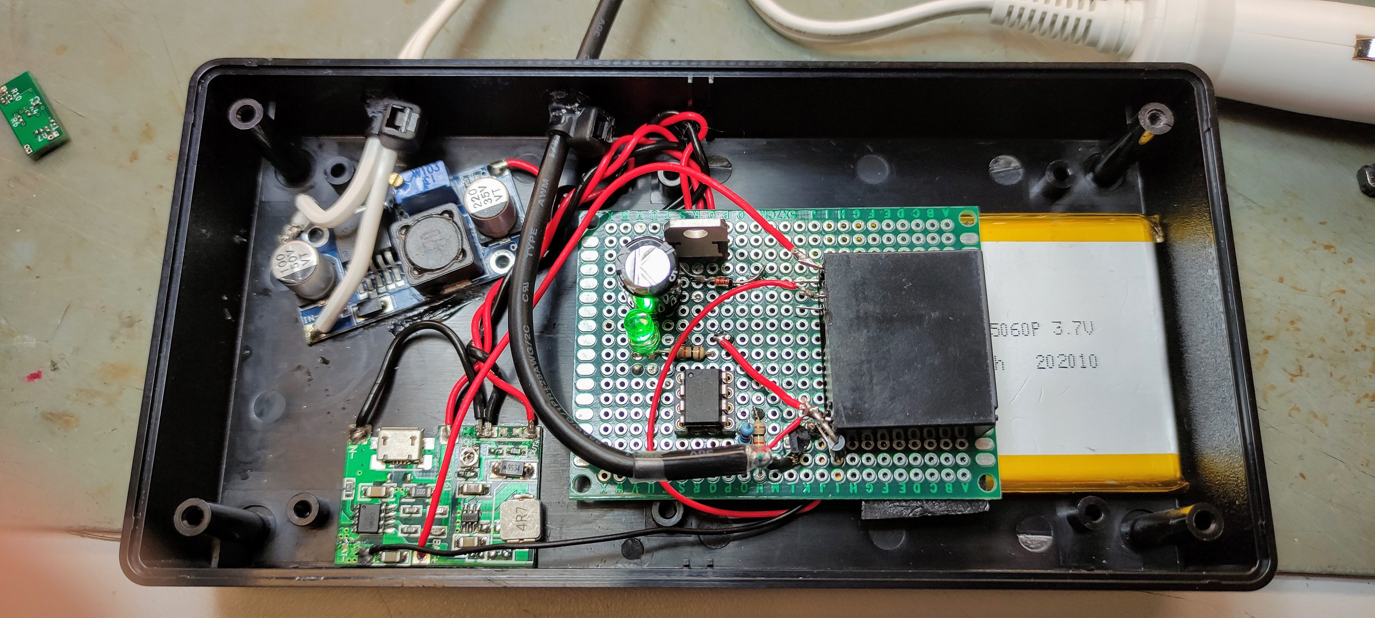
And finally put into the clutter box in the car, and connected up. It performs faultlessly ...


Which is a good job, because this is the state of the wiring on the old USB supply I'd just removed 😬

Friday 2 July 2021

Yet even more Raspberry Pi NOAA (& METEOR) fun

Well, it had to happen. The Pi Zero reeiver at Evesham promptly refused to talk to our old server a while ago, and the Cheltenham receiver had been disconnected for some time whilst a workshop re-organisation went on.

This morning, the Evesham receiver, rebuilt with a Raspberry Pi 4, and now sporting Raspberry-NOAA-V2


It's comprehensive files can be found here : https://github.com/jekhokie/raspberry-noaa-v2

It's really easy to install, with a couple of caveats. 

When you run install_and_upgrade , it takes a long while to run, even on a Pi4. I thought it had hung up. It hadn't... ! If a setting is altered, it runs much quicker on subsequent occasions!

It failed to install the correct blacklist file. I simply copied the file from the old receiver, and all is well.

It's got a fabulous in-built web console, and it's currently configured to drop it's pictures automatically to a new web page at https://doznoaa.blogspot.com/

- UPDATE - I appear to have upset google, and had posting limited for both the noaa blog, and this one ... another solution is required! I've removed doznoaa... pity it worked well.


The Evesham antenna hasn't changed, and still produces noisy pictures, I doubt it'll ever decode METEOR M-2. I'm planning a QFH in Cheltenham one day !

I'll get the Cheltenham receiver up and running soon... 

Sunday 21 March 2021

The ESP32 Analog (Analogue!) Clock

As promised, here's the new stupid analogue clock. 

It consists of two 270 degree analogue meters, thoughtfully calibrated 0-70V and 0-300A, kindly donated by Andy from North Hill Audio in Malvern, and an ESP32 with it's nice in-built RTC, wifi etc etc...

The idea is almost identical to the previously stupid analogue clock, found here. This time, we will use the ESP32's built in wifi to connect to the internet, and pick up the time from an NTP server, and set the ESP32's inbuilt RTC. There's an example in the ESP32's arduino library to do this, and utilises the standard time.h library to maintain the clock. I'll set a random time to refresh the RTC randomly between 12 and 24 hours, I don't want to keep bothering the NTP server. I can then output hours and minutes using PWM to drive the meter movements. 

First off we're going to need to do something about the scaling on our meter movements, as I can't easily drive 0-70 volts, nor 0-300 amps! 

Examining the meters shows the 0-300A meter is actually a 75mV full scale deflection meter (FSD), designed to be used with an external shunt of 0.025 ohms (or does it ... read on), this is good, as we can easily drive that.

The 0-70 volt meter reads directly. Disassembling it shows it has a "multiplier" resistor (actually 3 resistors in series, one adjustable) with the earthy end of the movement. 


Shorting out the multiplier gives us a meter with about 200mV FSD, perfect. The meters are dated 1972.
Both meters pull a fair amount of current ... 

A schematic is conjured up. There's not much too it.

As ESP32 has no native support for analogWrite, but we can use the ledc function. I don't care it's not driving an LED, and neither should you 😉. Each output pin, feeds the base of BC547 NPN transistor which is driving the meter. There's a 1K pot in the emitter to allow FSD for the meters to be set accurately. The venerable 7805 regulator supplies our +5V to the ESP32 and meters. 

There's an output on IO18 for a PM indicator LED, and an output on IO15, which I'm going to use to drive a relay, to give the clock a ticking sound ...

The script has some differences to the original ATMEGA328P script, as there's no 409Hz interrupt timing required, as the RTC is doing that job for us, and the code to receive the 433MHz timing signal has now gone, as that's now taken over by NTP. There's a section to extract the individual hours, minutes and seconds from the RTC, and load them into separate variables that we can manipulate. There's also no "smooth" function, as both hours and minutes are smooth, and there's no 400Hz interrupt timer to give us 1/409th of a second to drive a "smooth" seconds meter, and there isn't one anyway! The clock is also permanently set to 12 hour mode, with a PM indicator on pin XX. I've retained the fabulous "IsBST" routine. It just works. If you're outside of the UK, you'll need to modify the code to suit your timezone.

The software can be found on my github page at https://github.com/andydoswell/ESP_32_analogue_clock

The electronics is mounted up on perf board.


So that's the electronics and software sorted. 

I ordered a wooden craft box from eBay to mount it all in.


A couple of stains and finishing oil are tried out on the inside... 


.. and while they dry, I use libre cad to make a cutting plan for the front. 


The template is printed out , and taped to the box.


The two holes are cut out for the meters


The box given many coats of finishing oil to bring out the grain, and give it some shine.

I had to get a bit creative when  mounting the meters, as I didn't have the original mounting hardware..


I added some redundant 19" rack handles as a stand. I'm pleased with the results.

There, and goodnight, it's 250 amps past 51 volts!


I notice there's a kickstarter, where you can now buy something very similar. 


Pyers read this last night, and has pointed out the value of the shunt is wrong. I simply glanced at the back of the 300A meter, and mis-read it... I had wrongly assumed 0.025ohms was the value of the shunt... But 75mV across 0.025 ohms only gives us 3A... not 300.
Reading the label correctly, it simply states "Use with external shunt" , and the 0.025ohms is "lead resistance". The shunt should be 0.00025 ohms for a full scale deflection of 300A. 

Thursday 25 February 2021

Moving on up from ATMEGA328 & Arduino. The ESP32 "Mexican wave" light chaser.

I've recently been looking at other microcontroller options for some upcoming projects. Arduino and the ATMEGA328 have been wonderful devices, but it's getting on a bit now. 

I've played with the very powerful Teensy range of controllers a little bit, and they're great, just, well, a bit pricey .... The audio functions they perform are, however, wonderful. Probably great "bang for the buck" ... I just really don't need that much bang!

A while ago, I visited the USA, and one guy there gave me a "Blue Pill" , a fast, 32 bit microcontroller, with plenty of IO. Sadly not much in the way of RAM, and support for libraries seems a bit lacking. It is, however, stupid cheap.

I seen & read a bit on the ESP32. Looks good, and is cheaply priced. I've bought a couple. The one thing that (sort of) lets it down is the absence of a simple analogWrite function to control it's myriad of PWM outputs. It does have 2 proper DAC's though. Thankfully there's a function called ledc, which is largely similar, but operates at a higher (5KHz) PWM frequency than Arduino uno (nano etc) 490Hz, which makes filtration a bit easier. It's got wifi, bluetooth, a magnetic hall sensor (why??), and a built in RTC, and probably much more!

A while back I built the Arduino analogue clock , and always intended  to incorporate two large 270 degree meters. I never got round to it. My intention is to modify the code to use the in-built RTC, synchronised by NTP via Wifi, and use that to drive the meters. Seems easy enough, and will be a good project to cut my teeth on. 

In the meantime, I've been playing with ledc to make a mexican-wave style LED chaser, to get the hang of things a bit. It's based on adding more channels to the example supplied in the Arduino IDE for ESP32.

Hang some LED's off the pins as listed in the code, with appropriate current limiting resistors (220Ohm), and enjoy.


/*
  LEDC Software Mexican wave
  
*/

// use first 8 channels of 16 channels
#define LEDC_CHANNEL_0     0
#define LEDC_CHANNEL_1     1
#define LEDC_CHANNEL_2     2
#define LEDC_CHANNEL_3     3
#define LEDC_CHANNEL_4     4
#define LEDC_CHANNEL_5     5
#define LEDC_CHANNEL_6     6
#define LEDC_CHANNEL_7     7


// use 13 bit precission for LEDC timer
#define LEDC_TIMER_13_BIT  13

// use 5000 Hz as a LEDC base frequency
#define LEDC_BASE_FREQ     5000

// fade LED PIN (replace with LED_BUILTIN constant for built-in LED)
#define LED_PIN_0      23
#define LED_PIN_1      22
#define LED_PIN_2      21
#define LED_PIN_3      19
#define LED_PIN_4      18
#define LED_PIN_5      17
#define LED_PIN_6      16
#define LED_PIN_7      15

int brightness [] = {0, 32, 64, 96, 128, 160, 192, 244, 255}; // how bright the LED is

int fadeAmount[] = {1,1,1,1,1,1,1,1}; // how many points to fade the LED by

// Arduino like analogWrite
// value has to be between 0 and valueMax
void ledcAnalogWrite(uint8_t channel, uint32_t value, uint32_t valueMax = 255) {
  // calculate duty, 8191 from 2 ^ 13 - 1
  uint32_t duty = (8191 / valueMax) * min(value, valueMax);

  // write duty to LEDC
  ledcWrite(channel, duty);
}

void setup() {
  // Setup timer and attach timer to a led pin
  ledcSetup(LEDC_CHANNEL_0, LEDC_BASE_FREQ, LEDC_TIMER_13_BIT);
  ledcAttachPin(LED_PIN_0, LEDC_CHANNEL_0);
  ledcSetup(LEDC_CHANNEL_1, LEDC_BASE_FREQ, LEDC_TIMER_13_BIT);
  ledcAttachPin(LED_PIN_1, LEDC_CHANNEL_1);
  ledcSetup(LEDC_CHANNEL_0, LEDC_BASE_FREQ, LEDC_TIMER_13_BIT);
  ledcAttachPin(LED_PIN_2, LEDC_CHANNEL_2);
  ledcSetup(LEDC_CHANNEL_3, LEDC_BASE_FREQ, LEDC_TIMER_13_BIT);
  ledcAttachPin(LED_PIN_3, LEDC_CHANNEL_3);
  ledcSetup(LEDC_CHANNEL_4, LEDC_BASE_FREQ, LEDC_TIMER_13_BIT);
  ledcAttachPin(LED_PIN_4, LEDC_CHANNEL_4);
  ledcSetup(LEDC_CHANNEL_5, LEDC_BASE_FREQ, LEDC_TIMER_13_BIT);
  ledcAttachPin(LED_PIN_5, LEDC_CHANNEL_5);
  ledcSetup(LEDC_CHANNEL_6, LEDC_BASE_FREQ, LEDC_TIMER_13_BIT);
  ledcAttachPin(LED_PIN_6, LEDC_CHANNEL_6);
  ledcSetup(LEDC_CHANNEL_7, LEDC_BASE_FREQ, LEDC_TIMER_13_BIT);
  ledcAttachPin(LED_PIN_7, LEDC_CHANNEL_7);
}

void loop() {

  for (int i = 0; i <= 7; i++) {
    ledcAnalogWrite(i, brightness[i]); // set the brightness of each led in the array
    brightness[i] = brightness[i] + fadeAmount[i]; // increase the brightness of each led
    if (brightness[i] <= 0 || brightness[i] >= 255) { // until it gets to 255, then reverse the direction of fade, until it gets to 0, and reverse again
      fadeAmount[i] = -fadeAmount [i];
    }
    delay (1);
  }
}


Saturday 23 January 2021

Arduino Audio Compressor.

As part of an upcoming project, I need to compress some audio a bit. 

Now there's plenty of analogue compressor schematics on the web, but a lot require obsolete FETs or odd ball lamps, shining on an LDR (the optical compressor). I fancied a different approach.

Here's the plan, audio comes in to the "top" of a digital pot (also known as an R-DAC), the pot is controlled by the arduino. The wiper of the pot is connected to out audio output. That way, we can use the arduino to effectively wind our pot up and down to control the level of the audio. 

The wiper of the pot also feeds a rectifier, and the resultant level sampled by one of the Arduino's analogue ports, and that value is processed to provide the control signal to the pot.

A schematic is scratched out...


Audio comes in on J1, C3 is a DC blocking cap as the audio is biassed to half of the 5v supply by R1 & R2. The audio then feed the top of our digital pot, U2, on pin 5. Pin 7 of our pot is the bottom of our pot, and is connected to GND. Audio emerges from the wiper of out pot on pin 6, there's another coupling cap, C9, and the audio is then biassed to half our 12V rail by R14 & R16. It feeds a buffer amp, U1B and is output via R15 & C11, and is referenced to gnd by R17.The audio also feed U1A, which has a gain of about 14, and boosts the audio up to a sensible 10 volts pk-pk or so. This is coupled via C8 to our rectifier (D1 and a small filter cap of 10nF. This then drives the ADC of the arduino on pin A0. I haven't really shown the power supply, but it's just a single 12V supply, the 5V being derived from the arduino's on board regulator.

The software, can be found on my github page, as usual  https://github.com/andydoswell/audio-compressor

There are some variables to play with, being Target, Avg, Attack and Decay. Play around with the values and get a feel for it.

One other thing I played with, was feeding U1A from the incoming audio, rather than the devices own output. It was possible to get the software to lose control and end up with no audio coming out, but it could be tamed.. I think this type is called a "feed forward" compressor, and again, worth some experimentation. 


Here it is lashed on a bit of breadboard. It performed surprisingly well, and quiet too.


Friday 11 December 2020

Ham radio digital modes interface.

Many moons ago I built an interface to connect my computer to my IC-706IIG transceiver so I could operate a digital mode, PSK31.
I don't do much operating really, but quite fancy coupling my new Raspberry Pi400 up to a radio and having a go with another digital mode, FT8 (I know, I'm a bit late to the party.)

So, the plan is to re-jig my interface and up-grade it a bit. 

First things first, is to work out what I did originally !

It's all a bit of a lash up of parts. 

There's a stipped out USB hub, which has 2 USB to serial adaptors plugged in, and a really cheap USB sound card connected. 

The sound card mic and headphone sockets feed two pots on the front panel to control RX and TX level..


... and onto this PCB, where the audio is isolated by two transformers and connected to the transceiver via a 9-Pin D.


One of the USB to serial converters is just gunged to the back panel. It's the socket on the right. This was originally interfaced to the transceiver to control it's frequency. It's redundant now, as I have USB CAT control leads. 


The other USB to serial converter feeds two optoisolators on the PCB, which are used as KEY or PTT to tell the transmitter to go into transmit. Why two lines to do the same task? Practically speaking, there's no difference between KEY and PTT, except KEY is traditionally meant to mean a morse code or telegraph key, and PTT or "Push to talk" for voice modes. Software generally requires one or the other, rarely (if ever) both, and is generally configurable in your chosen software package anyway, so the RTS or DTR of the serial port can be specified to trigger transmit, as either PTT or KEY. 

A decision is made to rebuild. I want to upgrade the little USB soundcard in there, as it's not a great performer. After doing a bit of research, it seems the Sabrant USB soundcard rates well, and is only £9.99 from Amazon. As pointed out above, there's little point in having two PTT and or KEY isolators, so I'll make one, and make it switchable between a DTR and RTS, and output as either PTT or KEY to two separate jacks.

Both the serial converters in the box can go. I will use an FTDI board to control the PTT, which has the added benefit of only having a 5v output, rather than +/-15V (although I somehow doubt the original RS232 converters actually did this, I may be wrong!). Also it will provide convenient access to a +5V supply to run a level monitoring circuit.

The FTDI board is wired up to give a 5V supply, GND, RTS and DTR outputs.

After a couple of false starts, it turns out that the RTS and DTR signals are inverted, active low, but this was resolved by re-wiring the opto isolator, using the FTDI to sink the current. Whilst this seemed like a good idea at the time, something rang alarm bells with me... a check of the datasheet shows I can only sink 6mA, so I use a couple of BC547 transistors to invert the output and drive the optocoupler. 

More false starts... lord only knows what the isolation transformers I have are, but they're not the right thing at all  (did the original box ever work at all? I'm damned if I can remember!). 


I order some small 1:1 600 ohm isolation transformers from eBay


and conjure up a schematic in Kicad ...
I've changed the BC547 transistors to their smd brothers, to maximise the available space. It actually turned out a bit smaller than needed, but that's no bad thing...


Because (this time) our transformers are 1:1, we may well need to add a bit of attenuation into the signal. This is provided by the four SIT (suit in test) resistors R1, R5 ( transmit audio) and R11, R12 for received audio. RV2 is going to be mounted on the front panel, so it connects via a three pin header. I also plan to connect another front panel pot before the input at J1, it's the same deal as RV2. You may notice the RTS and DTR lines are coupled together. I'll feed one or the other from a change over switch. 

May as well design a board ...


I do love Kicad's 3d modelling. It's not just pretty, its great for polishing the layout of labels etc..


The gerbers are sent to JLC PCB for manufacture, and after a little wait for delivery, arrive. 


A little while is spent mounting the components. 
The four SIT resistors are set for no attenuation to start with. (R11 & R1 S/C, R12 & R5 O/C)


... and as usual, an error is spotted... thankfully it's just on the legend for the FTDI, the 5V and GND are reversed! 


It's all wired up into the enclosure... I'll tidy it up later, after we're happy with the performance...


WSJT-X is loaded up onto the Raspberry Pi400, and set up, the interface connected to my FT-817, and we're decoding!


The two trimmers are adjusted on the PCB, to give an indication of level on the LED indicators...

Incidentally, my friend Pyers 3D printed the front and rear panels for me.


There's an issue though... the FT-817 won't transmit :( 

The PTT is working just fine, but there's no modulation.


A fair amount of time went into checking and re-checking cables, and audio levels, then caution was thrown to the wind, and the FT-817 gets it's first ever factory reset in the many years I've owned it... after resetting menu 26 to USER-U , it bursts into life and transmits. 

A few minutes later and our first QSO on 2m (144MHz) is complete, with Stuart, G0LGS a few miles down the road in Cheltenham.  

PSK reporter also reports my tiny signal is being heard just outside of Cork, in Ireland, and, although I can't hear him, that's not bad for 5W into a discone antenna!

I've got a number of boards left over... if you'd be interested in one, drop me a line.

Sunday 8 November 2020

An experimental Arduino VU meter (and why it's no good)

 In an upcoming project (that is, as usual, taking far too long) requires some indication of audio input level.

So the plan is to have a meter, only this time drive it using an arduino PWM output. Seems like a good plan, as I already use said Arduino to perform one task on start-up, and it's sat there doing nothing most of the time.


So here's the simple input stage. It's job is to take our audio, and amplifying it, so it swings the whole range of our 5V rail, using a rail-to-rail opamp, and centering it on 2.5V, so it doesn't go negative. This is then fed into A0 of our arduino.


Now I need a peak value of our audio, so the usual trick is to rectify it. Rather than implementing this as , say a precision full wave rectifier, I thought I'd have a go in software.

Now the software reads the ADC, and if the result is greater than 512, the result stands and has 512 subrtracted from it. If the result is 511 or less, it's inverted and the result stands, IE is the ADC returns 0, it's inverted to 511, if it's 511, it's inverted to 0. That way, if our peaks are positive or negative, we're measuring a peak. It's a software rectifier.

And that's about all we care about. the output is divided by two and sent as a PWM to the meter. There's a bit in the software to decay the pointer.

At first glance, it appears to work well, given the limitations of the ATMEGA328's A/D ... but it's frequency response is awful...

The problem is with aliasing. Mr Nyquist tells us that we need to sample at least twice as fast as our highest frequency. The software may be going as fast as it can (albeit I haven't employed any techniques to optimise it) , but it's frequency response is poor, and unpredictable (or is it?)

Here's a quick video to show the issue... 

So it is predictable, and poor. Because we are sampling at a constant rate, at anything but that frequency, we will not be sampling the same point of our sinewave, let alone the peak, we could be sampling on the slope, or even at the central crossing point, and giving false readings. We can also see the frequency response improving at the higher frequencies. This is called "spectral folding" , and you can learn more about it here.

So there it is ... it might be OK to give a sort of visual response to some music, but it's woefully inadequate for my purposes. I could use a faster micro (and a better A/D), but that's overkill for this project. I've going back to doing this in good old fashioned analogue!

Here's the code if you fancy playing with it...

int LPeak;
int LoopCounter;

void setup()
{
  pinMode (5, OUTPUT);
  pinMode (3, OUTPUT);
  analogWrite(3, 255);
  delay (1000);
  analogWrite(3, 0);
}

void loop() {
  unsigned int Raw = 0;
  for (int i = 1; i <= 5; i++) {

    Raw += analogRead(A0);

  }
  Raw = Raw / 5;

  int LVal = Raw;

  if (LVal >= 513) {
    LVal = LVal - 512;
  }
  else {
    LVal = map(LVal, 0, 512, 512, 0);
  }
  LVal = (LVal / 2) - 1;

 if (LVal <= 35) {
    LVal =0;
  }
    //LVal =  (106* log10 (abs(LVal)));
  //Serial.println (LVal);
  if (LVal > LPeak) {
    LPeak = LVal;

  }
  if (LPeak >= 210) {
    digitalWrite(LED_BUILTIN, HIGH);
  }
  else {
    digitalWrite(LED_BUILTIN, LOW);
  }
  if (LPeak >= 229) {
    digitalWrite(12, HIGH);
  }
  else {
    digitalWrite(12, LOW);
  }
  if (LPeak <= 32) {
    LPeak =0;
  }
  analogWrite (3, LPeak);
  if (LoopCounter >= 1) {
    LPeak -= 1;
    LoopCounter = 0;
  }

  if (LPeak < 0) {
    LPeak = 0;
  }
  LoopCounter ++;

}

Sunday 16 August 2020

Arduino TV clock with vintage clock source (or another stupid Arduino clock, or "The Ping-Pong Clock")

A while back, the boss presented me with a gift ...


"Found this, I thought you'd like it"


It's a pair of 460KHz Crystals in a standard B7G glass valve envelope. Pretty.


It's sat on my desk for months ... I keep looking at it, and wondering what to do with it...

About the same time, my mate Alan gave me a small CRT video monitor.


I think it's come from a reversing camera from a lorry...


After working out the power pins on the rear, it springs into life, and a stupid plan is hatched....

Take the crystal, and build a CD 4060 oscillator/ripple counter, divide the output down to produce ~28Hz (460000/16384). Feed the 28Hz into an Arduino interrupt pin, and get it to run a clock. Run the TV out library as well, and produce an image on the screen. Brilliant. Stupid. All in one go.

Now, with a crystal oscillator, we need to know the crystal's "load" capacitance. This is formed by the two capacitors off each crystal leg to ground. Every crystal needs these. Get it wrong, and it's unlikely to reliably oscillate (if it does at all). For example, the usual Arduino crystal of 16MHz needs about 22pF on each leg to reliably start up. We'll also need to bias the 4060 so it always starts. Regular readers of this blog will know I used to include a 1 megohm resistor (unnecessarily) across the arduino crystal in my stand-alone designs. We'll need this in our oscillator. (We didn't in the ATMega328 because the bias is supplied by the IC). We'll also need a load resistor. The load resistor is there to make sure there's a voltage on the crystal with which to start the oscillation.

The issue we have is we have no idea of the load capacitance required, or it's required load resistor. There's a rule of thumb about load resistors. 1mm thickness of crystal = 1K ... our crystal is a little over 1mm thick, let's opt for 2.2K. Capacitance? No such rule of thumb. I was going to put 2 adjustable 100pF capacitors in each leg, and twiddle until it would reliably start. Sadly, I could only find one 100pF capacitor... so that went in one leg, and a 22pF fixed capacitor on the other.

Result? Nothing. No amount of twiddling of the 100pF capacitor helped. OK, add another 22pF capacitor to the circuit to give 44pF ... and it's oscillating, but it frequency isn't stable. Remove the two 22pF capacitors and replace with 100pF ....


... and bingo! ... 28.061 Hz pops out of the Q14 pin. It's reliable and steady as a rock. It's a shade off frequency, but crystals do tend to drfit with age, and I doubt my load capacitance quite meets the original spec. It should be 28.076171875Hz.. (460000/16384)


It's all built "fugly" style on a bit of perf board.


Here's the circuit

The pulses are fed into an Arduino Uno which allows a bit of development to go on, and a discovery is made (should have read the read.me!) .... you can't use an interrupt when using the TVout library, as the interrupts are being used to generate the timing need for video ... no problem, we'll use another arduino to generate the video and pass the data to it over a serial interface..


Now Arduino no1 is just doing the final bit of dividing down and outputting seconds over it's hardware serial interface, it's given it's own 16MHz crystal and mounted on the perfboard along with a 7805 to provide the 5V. The Arduino Uno is now used to develop the video software.


Before long, we have a rather nice clock display running.... (The photo doesn't do it justice, this is the tiny colour monitor I use in the workshop, and the photograph has artifacts..) . There's still plenty of memory left though ....


How about an animated "Pong" (Copyright Atari, the dawn of time) clock? Oh this is getting silly... Yeah, OK...

There appears a number of Arduino "pong" clones on the web, that will (allegedly) sit happily with TVout. After trying, I can't find one that works properly. Shoddy ball/bat collision (it's at best hit and miss 🤣), the ball flying right through the bat half the time.. we don't want that, so I re-engineered the code to suit.

Next thing... We don't want the monitor on all the time, consuming power and wearing the CRT cathode out. So some means of switching on the monitor when someone maybe looking at it. I did contemplate using a passive infrared sensor (PIR), but that's overkill. A simple sound detector will do. We can implement this on Arduino 1. 

A small electret microphone is amplified using an op-amp, and the output fed to Arduino 1's A0 pin.
This input is measured a few times, averaged, and compared to a value. There's an interesting bit of code here, whereby the audio is "rectified" in software, this means any negative audio is "flipped" over,  and a negative peak has the same value as a positive one (I've got a cunning plan for this bit of code, watch this space...). Anyway if this level increases above a certain point, there's some noise about, and we can switch our monitor on.


The output pin feeds a BC547 transistor, which in turn switches on a P-channel FET as a high-side driver, which supplies 12V to the monitor. A minimum on time is specified, as the monitor takes 8 seconds for the CRT cathode to warm. Even with the monitor off, Arduino 2 is still doing it's thing and creating the video waveforms and dealing with time.  


A temperature sensor is added to display the temperature as well... 

This is connected to A0 of Arduino 2. It's just a cheap 10K NTC thermistor. 


Meanwhile, we need a method for setting the clock. 3 push buttons are added, one for hours, one for mins and one for set, and connected to Arduino 2. When Arduino 2 starts up, it automatically enters this screen, and the hours and minutes can be set with the buttons. Once the set button is pressed, a reset pulse is sent to Arduino 1, and it's restarted, setting the seconds back to zero.


I also added a bit of code to enable easy calibration of the clock. Grounding pin D6 (pin 12 on the actual microcontroller) puts Arduino 1 into a calibration mode, whereby it outputs minutes elapsed since start-up and seconds over the serial interface. Disconnect Arduino 2, and connect Arduino 1 to an FTDI converter and monitor the serial output. Open the arduino monitor , and enable time stamp. Write down the time the sketch started, and the difference between that and the current elapsed time. Leave it for hours, then calculate how far it's drifted and use this value to alter the calibration value in Arduino 1 (old cal factor * ( number of seconds expected / number of seconds counted) . Excellent, it now keeps good time.

Excellent ... what about a chime?

I don't want just a beep or something from the micro... I'd like a proper chime.

(It's at this point, it begins to dawn on me I may have taken leave of my senses...)

A small solenoid is purchased from eBay... 


...and a bicycle bell...


.. all conjured up into a chiming assembly! 


... and a driver circuit created to be driven from Arduino 2.


So the final thing looks like this ...

The vintage crystal is top left, with the 14 bit ripple counter to it's right, and the 7805 voltage regaultor to the right of that.  The horizontal ATMEGA328P is our seconds generator, and controls the power to the monitor, the microphone and amplifier can be seen just below it. The high side FET is there too, and runs very cool, as the monitor draws about ~520mA when running. The vertical ATMEGA is creating the video, and also drives the chime, via the low side FET under the stripey ribbon cable, which leads off to the three push buttons, hours, minutes and set. Video is connected to the monitor via the small coax just above the ATMEGA.

The final schematic.


The clock display itself has three modes.


Clock ...


... pong ...


 ... and 3D cube ...


The software can be found, as usual, on my github page https://github.com/andydoswell/stupid-video-clock , and I've included the TV out library as well, as I've modified it so it compiles without issue, has a "degrees" symbol and tweaked the timing a shade. 

Now, I'd better start thinking about a case for it... some sort of perspex thing?

My colleague , Alan, has given it a good name... "Well, it goes "ping", and plays "pong" ... it's the ping-pong clock" 😁