Translate

Showing posts with label Audio. Show all posts

Sunday 6 December 2020

NAD 3020 repairs

The famous George rang.

My NAD's developed a nasty hum, can you have a look?

Yeah, why not...


It's the very excellent NAD 3020.

A particular favourite of mine. These must have been one of the best selling amps throughout it's life...

(There's even a wikipedia article on it here.)


Now, many of these are getting a bit long in the tooth now.... and George's is no exception.

I switch it on, and there's some awful humming which just won't go away. Some of these amps suffer with a hum on switch on, which disappears after a few seconds, after frightening the user. We'll come back to that later.

Remove the screws on either side, slide the lid back slightly and lift it off...


One feature of this amp is the shelf at the back, where all the connections are located. Makes access easy if you're fishing around around the back. It's not without it's issues, however...


Turn the amplifier upside down, and remove the base plate (8 screws, short one's in the middle!) 


This is the underside of the connection "shelf" ... dry and broken joints are normal here, so solder the lot up...


There's some caps showing signs of their age, and have failed. I'm going to change the usual suspects..


... as well as the four main smoothing caps.


You'll need to pull the knobs off, and remove the four countersunk screws securing the front panel, and remove it ... be careful to support it, as we don't want to go to the hassle of removing the power meter's ribbon cable. The power LED will pull out.


Remove the screw securing the brace bar behind the front panel..

... and the other screw securing it on the back 


Two screws attaching the PCB to the brace bar, one through the heatsink.....


and the other towards the rear ...


You can now remove the brace bar to access the whole of the PCB. 


So after a quick cap change (there's 4 2,200 uF 63V caps, two 1,000 uF 6.3V caps (I fit 16V types here , I don't trust those 6.3V elctrolytics!) and two 330uF 63V caps...) 


(The other 330uF 63V is hiding!)


..things are much improved, but there's another fault... I mentioned it earlier. When you initially switch the amp on, there's a very unpleasant hum which decays, leaving the amplifier performing ok.. it's like a "whomp" as it turns on. It's a very common fault...


It's caused by this capacitor (and sometime's its neighbour too). I change them both for 47uF 63v types... whomp gone!


Bias is checked , and is spot on. Just got to button it up, and give it a good testing with "The Lasters" by Fred Deakin.

The guilty parties... 

Sunday 8 November 2020

An experimental Arduino VU meter (and why it's no good)

 In an upcoming project (that is, as usual, taking far too long) requires some indication of audio input level.

So the plan is to have a meter, only this time drive it using an arduino PWM output. Seems like a good plan, as I already use said Arduino to perform one task on start-up, and it's sat there doing nothing most of the time.


So here's the simple input stage. It's job is to take our audio, and amplifying it, so it swings the whole range of our 5V rail, using a rail-to-rail opamp, and centering it on 2.5V, so it doesn't go negative. This is then fed into A0 of our arduino.


Now I need a peak value of our audio, so the usual trick is to rectify it. Rather than implementing this as , say a precision full wave rectifier, I thought I'd have a go in software.

Now the software reads the ADC, and if the result is greater than 512, the result stands and has 512 subrtracted from it. If the result is 511 or less, it's inverted and the result stands, IE is the ADC returns 0, it's inverted to 511, if it's 511, it's inverted to 0. That way, if our peaks are positive or negative, we're measuring a peak. It's a software rectifier.

And that's about all we care about. the output is divided by two and sent as a PWM to the meter. There's a bit in the software to decay the pointer.

At first glance, it appears to work well, given the limitations of the ATMEGA328's A/D ... but it's frequency response is awful...

The problem is with aliasing. Mr Nyquist tells us that we need to sample at least twice as fast as our highest frequency. The software may be going as fast as it can (albeit I haven't employed any techniques to optimise it) , but it's frequency response is poor, and unpredictable (or is it?)

Here's a quick video to show the issue... 

So it is predictable, and poor. Because we are sampling at a constant rate, at anything but that frequency, we will not be sampling the same point of our sinewave, let alone the peak, we could be sampling on the slope, or even at the central crossing point, and giving false readings. We can also see the frequency response improving at the higher frequencies. This is called "spectral folding" , and you can learn more about it here.

So there it is ... it might be OK to give a sort of visual response to some music, but it's woefully inadequate for my purposes. I could use a faster micro (and a better A/D), but that's overkill for this project. I've going back to doing this in good old fashioned analogue!

Here's the code if you fancy playing with it...

int LPeak;
int LoopCounter;

void setup()
{
  pinMode (5, OUTPUT);
  pinMode (3, OUTPUT);
  analogWrite(3, 255);
  delay (1000);
  analogWrite(3, 0);
}

void loop() {
  unsigned int Raw = 0;
  for (int i = 1; i <= 5; i++) {

    Raw += analogRead(A0);

  }
  Raw = Raw / 5;

  int LVal = Raw;

  if (LVal >= 513) {
    LVal = LVal - 512;
  }
  else {
    LVal = map(LVal, 0, 512, 512, 0);
  }
  LVal = (LVal / 2) - 1;

 if (LVal <= 35) {
    LVal =0;
  }
    //LVal =  (106* log10 (abs(LVal)));
  //Serial.println (LVal);
  if (LVal > LPeak) {
    LPeak = LVal;

  }
  if (LPeak >= 210) {
    digitalWrite(LED_BUILTIN, HIGH);
  }
  else {
    digitalWrite(LED_BUILTIN, LOW);
  }
  if (LPeak >= 229) {
    digitalWrite(12, HIGH);
  }
  else {
    digitalWrite(12, LOW);
  }
  if (LPeak <= 32) {
    LPeak =0;
  }
  analogWrite (3, LPeak);
  if (LoopCounter >= 1) {
    LPeak -= 1;
    LoopCounter = 0;
  }

  if (LPeak < 0) {
    LPeak = 0;
  }
  LoopCounter ++;

}

Friday 6 November 2020

Rockit 6 RPG2 repair

Mike brought me a speaker in.... 

"This belongs to my mate, he says it's crackling, can you have a look?"

Yeah ... why not?


It's a Rockit monitor. 

Sure enough it's popping and crackling ... off with those 8 screws on the edge of the back panel, and carefully remove...


Usual idea, amplifiers (in this case two, one for the tweeter, one for the sub) and transformer/ active cross over all built onto the back panel...


The fault is immediately obvious... the dreaded black goo ... This is some sort of adhesive applied liberally to the pcb to stop the capacitors and other large components "falling out" because they don't trust their soldering (this is a somewhat sarcastic guess, but I fail to see any real reason for it!)  It has an issue. After a time, if it's got hot, it can start to conduct, causing undesired operation of the device. I see it quite often.. for example here.


I can see it's got very dry and crusty (and most likely conductive) in a couple of places. Most noticably here ... we'll have to clean it all off to make a reliable repair. The dry stuff mostly chips off.... 


The rest needs a soak in a bit of acetone (or nail varnish remover), I add a bit to bits of kitchen roll, and allow it to soak in for 30 mins, and the goo just wipes off... 


Get as much off as possible. 


... and reassemble. Simple fix. 

I warned Mike the other one would need doing as well, and cleaned that one up too...

Sunday 17 May 2020

Video rack repairs and new video multiplexer upgrade!


5 years ago, I built a rack to house the standards converter and video source equipment in the workshop (you can see that post here)... it's time for a few repairs and a refresh.


It's got a few niggling faults.

1. The DVD player no longer ejects, and sometimes doesn't want to play.
2. There's a couple of channels which no longer work
3. There's quite a lot of crosstalk between channels.

Let's address a few of these...

1) The DVD ...


First off some disassembly of the rack case, which allows the DVD player to be removed.


Powering the player up, and there's nothing on it's output... until after a few minutes the unit powers up, and reports "Bad disc" on it's on-screen display...


A few screws later, and the lid's off, the tray front removed and the trapped disc released.


A known good DVD is inserted. At this point it's obvious why the thing won't eject. I suspected a failed tray belt, but that wasn't it... the tray is catching on the front escutcheon. I'll deal with that later. The disc attempts to spin up, fails miserably to get to speed, and then "Bad disc" appears once more.. On the second attempt the player seems to re-start it's firmware...

I check the outputs from the power supply with my multimeter... +5, -12 and +12.. +12 is varying between about 10.5 to 12.5, which may be acceptable. I switch to the 'scope and check the +5V again....

Woah! That's awful - 40V pk-pk of 50Hz crap riding on the output !


The power supply is removed, and a blanket change of all the electrolytic capacitors is performed, to ensure reliability.


The power supply is replaced, and on powering up, the disc spins up rapidly, and then reports "No Disc" ... hmmm ...


The laser pick up is given a gentle clean with some window cleaner (Don't use IPA on any CD or DVD, it damages the coating on the lens), and ....


Bingo, the test pattern DVD fires right up!


The guilty parties....

The sticking front tray is resolved by relieving the front a touch with a file... I suspect it's got distorted by the shelf above it in the rack for all those years...

Good, one fault fixed ... on with the next...


2 & 3 - Channels not working and crosstalk.

This is being caused by the mechanical switches failing on the front panel, there was always a bit of cross-talk (one channel seeming to "float" behind the video of another) as the switch does not provide any correct loading, or buffering between channels... 

What's needed is a proper video (and, of course audio) multiplexer.


I designed this a while ago in Eagle... thankfully Kicad reads eagle files :) KiCad, the gift that keeps giving :)

There are 8 audio and video inputs. 

Each video input is loaded by a 75 ohm resistor, and fed to two MAX4312ESE multiplexing ICs. One outputs the video to a UHF modulator, and one outputs the video to a 625/405 line standards converter. So, under the control of my favourite flavour of microcontroller, the ATMEGA328P, any of the video sources can be sent to either 625 or 405 sources.

The select line of the video multiplexer also feeds two ADG1408Y multiplexers, which switch the audio through to the relevant output device in the same manner. There's a 5532 buffer on the audio output, as there's none in the audio mux, unlike the video mux.

The audio mux requires a negative supply rail, and this is supplied from the microcontroller. A continuous squarewave is output on pin 5 of the micro, is floated by C9, and rectified by the double diode D1 (BAT54S) to provide a "-5V" supply, in reality it's more like -4V. 

The micro is controlled by a front panel , which has two push buttons, and a small OLED display.

A PCB was created... not modelled as it was Eagle, but Kicad has a go at it!

When Kicad imports an Eagle creation, it doesn't seem to cope with the ground plane or component models, but you get the idea... 


... anyway, the real thing turns up from PCBWay.

... and duly stuffed. I'll clean that flux up later ;)
The front panel was also designed. Simple.
and again, built up... not quite so simple though, as my new display has the power and ground pins reversed from the one I modelled :(


... so a minor bodge is deployed...


The software is very straight-forward. It acts conditionally on the actions of the select switches on the front panel to increment the channel address selected, and update the display. I used the U8glib library this time out, as it's got some nice fonts, and is quick, if a bit bulky.

The software can be downloaded from my git. https://github.com/andydoswell/video-rack

It will be noted that the hardware supports 8 inputs, and two outputs, but the software doesn't support that many, as I don't need them all! It's a simple task to enable more, if you wish.


Nice font...


So, back to the rack.


Out with the old...


Tidy up the RF wiring a bit. The black box in the bottom is the Aurora 405 line standards converter. The loop of co-ax you can see is a stub filter, as the output from the aurora is very harmonically rich, and the filter eliminates aome of the patterning caused by the harmonics effecting the UHF. What I really need is a low pass filter .... one day.


The UHF modulator (modified to run on DC, see here) is once again disassembled, so I can adjust the channel and sound carrier spacing via two buttons on the front panel. I've just soldered some wires on the existing switches, and made them available to the front panel.


The Cyclone media player, and HDMI converter are mounted on the shelf, and the multiplexer PCB behind that.


The power supply is a salvage 12V 5A supply. This feeds the multiplexer, and the aurora. It also feeds the modulator via a 42 ohm resistor (to give about 8V) , and an eBay 5V buck regulator, which feeds the Cyclone and HDMI converter.


The front panel is marked out...


... and the holes chewed out with my teeth. I do wish my metalwork was better, anyway, it's only for my own consumption!


And it's all wired up ... what a rat's nest!


The back's fitted, and it's all powered up and tested - No cross talk, all the inputs work - oh bliss!


Now, there's a rake of telly's here need fixing ....

Saturday 28 March 2020

Hospital radio streaming codec and monitor.

Things have been getting a bit, well, unreliable at the hospital radio studio of late. We've been plagued with power outages, and things don't recover well.

Mainly the old Ubuntu 16 box, which supplies shoutca.st with the MP3 stream.

It usually comes back on OK, but half the time fails to run the darkice service on start-up. No amount of fiddling the cron job that starts the service has helped.

What's needed is a system that checks and monitors itself, and attempts to repair what's broken.

Here's what I've got in mind.

Two Raspberry Pi's, one transmitting, one receiving. The receiver will be monitored to ensure that the stream is up.

The Pi's audio will be fed into and internet-equipped Arduino of some description, which will do the monitoring for us.

It'll work something like this:


  • If the received audio is ok, do nothing. All is well.
  • If the received audio is missing, check there's audio coming in to the transmitter. If there isn't then there's nothing we can do except to flash a "something's up" LED to get someone to fix it.
  • If the received audio is not present, but there's audio to the transmitter, check there's internet access; If there isn't there's little we can do, except for flash a "something's up" LED and wait for it to come back. If there is, then we need to take some action:


  1. Shut down and restart the receiver, just in case it's crashed. If that doesn't work, then ...
  2. Shut down and restart the transmitter, just in case that's crashed.


OK, so there are a good few guides on getting internet radio receivers to run on a headless Pi. I've tried a couple, and have found one that is very tolerant of dodgy internet connections, it's called mplayer, it's a bit processor hungry for what it is, but runs on a model A+ Pi I have.  It comes back if the internet goes missing as soon as it recovers, and starts reliably on boot. I did this a while back, and it's been sat on the workshop shelf for ages, reliably receiving :)

It's dead easy to install..

apt-get install mplayer

add a cron job...

crontab -e

and add the following line...

@reboot     sleep 29; nohup mplayer -loop 0 http://188.165.192.5:8525/stream 2>&1 > /dev/null

(replacing the IP address and mount point with your own, unless you want to listen to Cotswold hospital radio!)

You may need to adjust the output volume.. Just type

alsamixer

adjust as required, then type

sudo alsactl store

to store the setting.

Now we need to add a bit of Python script in to safely reboot the monitor receiver in the event of a failure, and also add a shutdown function, so we can safely shut our unit down, without risking corruption of the memory card.

We are going to use the Pi's GPIO pins 18 and 23. Pulling 18 low will instigate a safe shutdown. Pin 23 will force a shutdown and restart.

I've copied the code from here, but duplicated it here as well, just in case it ever goes missing.

First off SSH into the Pi...

Once logged in, type

mkdir Scripts

cd Scripts

touch shutdown_pi.py

sudo nano shutdown_pi.py

Then cut and paste this code into the editor.

#!/bin/python
# Simple script for shutting down the raspberry Pi at the press of a button.
# by Inderpreet Singh https://www.element14.com/community/docs/DOC-78055/l/adding-a-shutdown-button-to-the-raspberry-pi-b

import RPi.GPIO as GPIO
import time
import os

# Use the Broadcom SOC Pin numbers
# Setup the Pin with Internal pullups enabled and PIN in reading mode.
GPIO.setmode(GPIO.BCM)
GPIO.setup(18, GPIO.IN, pull_up_down = GPIO.PUD_UP)
GPIO.setup(23, GPIO.IN, pull_up_down = GPIO.PUD_UP)

# Our function on what to do when the button is pressed
def Shutdown(channel):
        os.system("sudo shutdown -h now")
def Restart(channel):
        os.system("sudo shutdown -r now")

# Add our function to execute when the button pressed event happens
GPIO.add_event_detect(18, GPIO.FALLING, callback = Shutdown, bouncetime = 2000)
GPIO.add_event_detect(23, GPIO.FALLING, callback = Restart, bouncetime = 2000)

# Now wait!
while 1:
        time.sleep(1)


Press CTRL + X and yes to save and exit

now type

sudo nano /etc/rc.local

and add this line just above the last exit 0

python /home/pi/Scripts/shutdown_pi.py &

now safely shutdown the pi

sudo shutdown now

wait for a minute and remove the power.

Remove the memory card and make an image of it and keep that safe, just in case...

Job done.

The transmitter is a new Raspberry Pi 3, and I followed the instructions here to load up darkice. I don't need to run icecast, as this is provided to us by remotely by shoutca.st, I just need to send the stream to them. I also ignored the warning about not installing the latest version of Raspbian. Seems to work great, never fails to start reliably, and seems to be tolerant of errant internet connections. You'll need an external USB sound card, as the pi's inbuilt card can't record.

Also, add in the shutdown and reboot python script in the same manner as before.

Image the memory card just in case!

Now our incoming audio is balanced, so we need a balanced line receiver, a buffer for the received audio monitoring, and whilst we're there, a couple of little drivers for some VU meters (because meters are cool), which we can also use to feed our Arduino monitor.

As an aside, I've now made the jump to Kicad, as since Autodesk have purchased Eagle, they no longer wish to honour my original Cadsoft licence, without incurring unwanted expense.

A circuit is conjured up ...


A board designed... 

And modelled ...
And turned into reality using toner transfer.
Loving Kicad...

U1 and U2 form the balanced to unbalanced audio receiver, and it's output level is adjusted by RV3. This then feeds the transmitting Pi's external sound card. There's also a buffer (U2A) which feeds a small monitoring amp. ICU2B is a variable gain precision rectifier, the output of which is used to drive the VU meter, and also feed one of the Arduino's A to D converters.

The same circuit is also duplicated and used to buffer the audio from our receiving Pi to drive the monitoring amp, and to drive a VU meter and the Arduino. 

There's a regulated +/- 15V supply. As it turns out I had a suitable switched mode supply, with +/- 12V and 5V outputs, so I utilised that, and just bypassed the regulators.

An Arduino nano was pressed into service, to do the monitoring and control.


Received rectified monitor audio is passed from the analogue PCB from the VU drive circuit to A0 , rectified transmitted audio is received likewise, and fed to A3. A front panel mounted LED is connected to Digital pin 3, to serve as our error indicator. I'll also make the Arduino Nano's USB interface available on the rear panel to facilitate debugging/ updating as required.

An Ethernet module (EN28J60) is connected to the Arduino's SPI interface, and is powered from a 3.3V regulator derived from the main +5V supply. The EN28J60 consumes around 120mA, and that's more than the available 3.3V supply on board the nano. The EN28J60 module is provided with network access from the same hub that distributes the network to the Raspberry Pi's.

Two additional outputs (D5 & D6) on the Arduino are used to pull a GPIO pin low on the respective Pi to initiate a graceful reboot, and D7 is diode "anded" to shutdown the two Pi's. A push button is connected to D2 to shut down the system. 

If it all goes really badly wrong, I've also added two reset buttons on the front panel to manually hard reset the Raspberry Pi's (and arduino, via a diode "and").

D4 is coupled back to the arduino's reset pin, to reset the controller completely. This is coded to happen if we fail to obtain a DHCP lease more than 5 times.
The VU illumination is connected to D8 via a BC547 transistor. This is used to flash the VU illumination during shutdown to give the user some feedback that shutdown is in progress.

In the event of failure of the monitor audio, the transmit audio is checked.

If the transmit audio has failed, the error LED on the front panel will flash 3 times. The monitor circuit will repeat these tests until audio is resumed.

If the monitor audio has failed, and transmit audio is present, the controller checks internet connectivity. If the internet connectivity is not present, attempts are made to restore DHCP. If this process fails, the fault is presumed to be external, and the error led will flash 5 times, followed by illuminating permanently. If the internet does not recover after 5 DHCP renew attempts, the controller will restart and repeat the process.

If the monitor audio has failed, TX audio present, and internet OK, two possibilities remain. Either the monitor receiver computer has crashed, or the TX computer has crashed. Firstly the controller will shut down and restart the monitor computer. If this fails , the TX computer is restarted.


A board is designed, but I've made it up on perfboard...


Arduino code can be found on my git https://github.com/andydoswell/transmitter-monitor

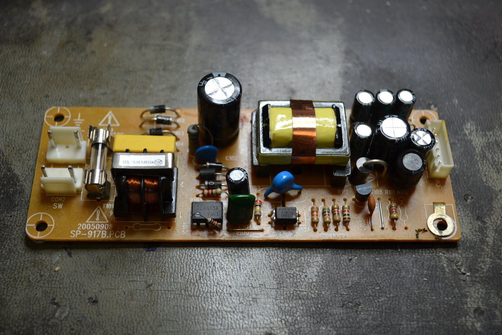
Power is supplied to the whole rack from a switched mode supply, recovered from some redundant equipment... It supplies +/-12V and 5V. Excellent.

Putting things together and running some tests, and there's an irritating 4KHz whistle on the audio, both transmitted and on the in built monitor amp... nasty

Scoping up the outputs from the power supply shows there's a 4KHz tone superimposed on our 5V rail. It's about 170mV, and enough to cause the annoying whistle. Tests show this isn't down to a failure in the supply (I suspected caps, but changing them out made no discernible improvement)

A simple C-L-C filter is quickly made up from some junque parts, and greatly improves the situation.

Much improved.

And the finished product, ready for installation once this damn virus goes away...