A not inconsiderable number of years ago, I bought a box of parts at a car boot sale for not a lot of money.
In amongst the wire-wound resistors, bits of tag strip, valves and other delights, was this small assembly....

I took it into college (it was that long ago) to see if it could be identified...
Most of the lecturers were a little puzzled at first ... "Pencil vacuum tubes?" , "Some sort of neon?" ... then one lecturer (whose real name escapes me at present, but we used to call him "Toke") identified them as geiger-muller tubes "Russian, by the looks". Top man... I wonder where he is today?
There are three tubes in total, designed to detect different energies of radiation.
 This side is fitted with a DOB-50 tube. There's scant information on the internet about this tube, except it seems to have been made in poland, and used extensively by the polish army.
It needs between 390-490 volts to operate, and the left electrode shown here electrode is positive.
 The top tube here is a DOB-80, again a polish tube, and there's more info about this on the web...
Operating voltage 490-590, and sensitive to Gamma, Beta and X-rays
The bottom metal tube is a CTC-5 (STS-5) and has CCCP on it, it's a hard beta tube, and has the date code for 1969 on it. It wants between 380V-480V.
After a bit more googling about, it seems I have the internals from a DP-66M dosimeter probe , as used by the Polish Army. Apparently, these have only become available on the market relatively recently, so I don't know what mine was doing in a box of junque in the 80's ... anyway, let's make it do some work!

So, two little switching power supplies, one for the DOB-50 and CTC-5 as they have similar operating voltages, and one higher voltage one for the DOB-80, a simple op-amp comparator to output the pulses to an Arduino to process and display the results.
The power supplies are controlled using two MC3406AD's, driving an IRF840. I'll just refer to the component numbers on the top supply, the bottom one is almost identical. The back EMF from the inductor L2 is rectified by a UF4007. There's a feed back loop, R14,15 & 16 and the pot is used to adjust the HT.. The supply is smoothed by a C-R-C filter C13, R19 and C14 (which is absent from the lower supply, I was concerned about the top supply driving two tubes) R22 limits the current into our tube's anode. R25 provides a load for the tube, and the output is fed to a comparator opamp, which drives Q5 via R29, and triggers the arduino input.
I've included a meter driver on the output of the arduino, for that authentic "3.6 roentgen, not great, not terrible" moment, a speaker output for added "China Syndrome" atmosphere, and an interface for an I2C display, for some actual empirical data.
 I've also added a pin to monitor the battery level.
A PCB is duly designed, and ordered from PCBWay.
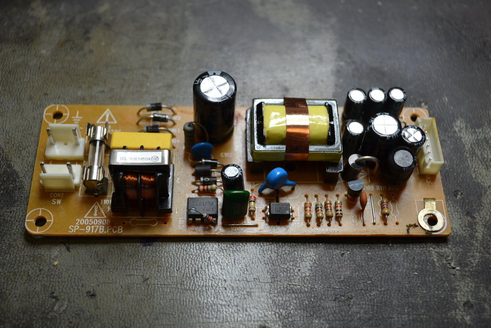
 A pleasant morning spent stuffing the board.... note some of the through hole resistors are mounted off the board, in an attempt to prevent them tracking to the ground plane.
Note I've not fitted the Arduino yet, let's get the power supplies sorted first.
First, measure between pin 5 of each power supply IC and ground and set each HT control to give the maximum resistance to ground, this should give us the lowest output voltage to start with.
Now we're going to be dealing with high voltages here, not a fat lot of current behind it, but it will certainly bite if not kill, so be wary.
Connect up a 5 volt bench supply, and current limit it to about 500 mA.
Something's very wrong with mine.... I can't adjust the output voltage above 290V, and my FETs are getting hot, and it's making a nasty buzzing noise. ... Checking though my work, and I've fitted 33nF and 22nF capacitors in place of C7, C3 and C1 resulting in the switching frequency being far too low..... thankfully nothing is damaged.
 Firstly set up the "top" power supply, measuring
the high voltage from R19 to ground.

 Now, following the same procedure for the bottom power supply, this time adjusting for 550V.
It's worth noting here, that removing the 5V supply to the board, the HT collapses very quickly to safe levels. There's not a fat lot of capacitance here to stay charged up, and the feedback loop discharges this quickly.
The more observant of you will notice that I've socketed the arduino. For some unexplained reason, I've got and used pin 0 and 1 for other things than serial coms, making it impossible to programme in situ. Silly.
 After a little bit of tweaking, I've got readings from the CTC5 tube, but nothing from either the DOB-50 or DOB-80. On closer inspection of the original board, on which the tubes were mounted showed the wiring to the tubes is very corroded. Using some sockets recovered from a DIL socket, I cleaned up the tube pins and connected straight to the tube.
Still nothing. I switched the CTC5 tube into the DOB-50 circuit, and it counts ... Sure enough further testing shows I've got two duff tubes, and looking at them under the microscope shows cracking around the glass where the pins enter... Damn. I suppose they've been kicking round in a box of junque for years, I shouldn't be suprised...
I've included the code for the triple tube in my github, although it's not anywhere near finished and does contain errors, feel free to use is as a starting block only. I'll concentrate on a single tube variant, as that's all I've now got...

I've added a link wire from arduino digital pin 7 to pin 3, so we can use an interrupt to count the pulses, rather than polling.
Software can be found on my github at https://github.com/andydoswell/geiger_counter
The pulses are counted. The instantanious Counts Per Minute (CPM) is based on the time elapsed between the last two pulses, also an actual CPM is calculated (the actual number of counts in the last minute), a long term average (since start up), and counts per hour.
The peak level is displayed on a meter, and decayed slowly in the software.
When the software is started, the meter displays FSD (allowing FSD to be set with R35) , and then the battery level.
 The meter display looks like this when in use... a couple of pulses in quick succession will give a high peak reading ... if it stays that way, begin to panic....
(Excuse the B&O VU meter, I had it to hand!)
 LCD display looks like this... Battery Level is displayed to left, followed by the instant CPM (CPM) and Actual CPM (ACPM). On the next line is a trend indicator, showing if the last Actual CPM is greater or less than the LTA (Long term average), and actual counts per hour (CPH) .
I'd like my counter to be portable, so I can wander round the countryside after the virus has passed, and scare people... So we're going to need a power supply, preferably re-chargeable.

I've got some of these modules from eBay, normally found inside small power banks. The USB socket is used to charge a single LiPo cell. This in turn, feeds a 5V boost supply. Almost ideal, except the 5V booster is always running, and although there's a protection circuit in it to prevent the battery volts falling too low and damaging the cell, I'd rather it was switched, so a modification is needed. You can see in the photo, the USB charging circuit is very much on the left of the board and the booster on the right...
All we need to do is cut the track that connects battery + and the booster, and fit a switch. We also want to monitor the battery voltage, so we can take this from there to JP7 (which feeds A0) on our PCB.
 First things first, connect a battery (I used a 18650 cell) and carefully set the output voltage to 5.0V using the small pot on the board, just below the output terminals.. Now remove the battery, and cut the track where marked on this helpfully annotated photo...
 And solder on some wires as shown... The green wires go to the on/off switch, and the thin grey wire goes to JP7 on the PCB, to monitor the battery voltage.
 A suitable (if a bit too big!) enclosure is ordered from Electromart2000 on eBay. I've had a few enclosures from them, and they seem to be of good quality, not too expensive, and made here.
 The front panel cut outs for the meter and display are drawn out in LibreCAD ...
 Imported into Laserweb ...
 and the front panel is laser cut with a 3.5W Laser etcher... Fume extraction on!
... it took a while!
This is speeded up 4000 times!

After an hour and a lot later , the front panel is finished.

The parts are still just held on, and are knocked out...

Looks good :) As I was now using a 50uA FSD meter, I added 91K in series with it, to allow adjustment to FSD using the pot on the board.
 The on off switch is added, the LED and speaker, then ....
... I knocked my one remaining good tube off the shelf and promptly stood on it. Suffice to say it no longer works. I'm not happy.
Still, gives me a great excuse to try some more :)
 Some different tubes are ordered from Russia. They take a while to arrive, due to COVID-19, but are superbly packed...
 Here's what I've bought, in comparison to the CTC5 tube I ruined...
Here's the spec for the SBM20 ...
Minimum Anode Resistor (meg ohm) 1.0
Recommended Anode Resistor (meg ohm) circuit diagram 5.1
Recommended Operating Voltage (volts) 400
Operating Voltage Range (volts) 350 - 475
Initial voltage (volts) 260 - 320
Plateau length (volts) at least 100
Maximum Plateau Slope (%/100 volts) 10
Minimum Dead Time (at U=400V, micro sec) 190
Working range (mkR/s) 0.004 - 40
Working range (mR/h) 0.014 - 144
Gamma Sensitivity Ra226 (cps/mR/hr) 29
Gamma Sensitivity Co60 (cps/mR/hr) 22
Inherent counter background (cps) 1
Tube Capacitance (pf) 4.2
Life (pulses) at least 2*1010
The huge SMB19 tube
Operating Voltage Range (volts): 350 – 475V
Initial voltage (volts): 260 – 320V
Recommended Operating Voltage (volts) : 400V
Minimum Dead Time (at U=400V, micro sec): 250us
Plateau Inclination: 0.1%/V
Working temperature: -60 to + 70 C
Counting speed: max. 2000 imp/s
Inherent counter background (cps) 1.83 Pulses/s
Interelectrode Capacitance 10pF
Load Resistance 5 – 10 MOhms
Sensitivity to gamma radiation:
MED – 3.0 mR ∙ s -1;
247.5 mR -1 ± 26mkR -1
Length: 195mm
Diameter: 18mm
The SBM 19 tube is apparently very sensitive...
Now we know how delicate these tubes are, I'm going to make some enclosures for them from some PVC pipe. I'll cut a window in the pipe, in an attempt to prevent any low energy beta from being absorbed by the pipe...
 34mm OD plastic PVC drain pipe, and end caps...
Window marked out, and ends drilled....

... and the window cut out with a rotary tool.
 Some dense packing foam (actually the foam the replacement tubes came in) is marked out, and some foam washers made to support the tubes.
The washers are (very carefully!) pushed over the ends of the tube...

... and pushed down inside the tube, along with a piece of wire to connect to the electrode at the other end...

I bought some PCB 6.3mm fuse holders which are just the job for fitting to the tube's electrode connector. Here's a tip, don't get them from eBay, they're very expensive. I got a pack from RS for much less money.

Nice ...

Repeat at the other end...

The end caps are the sort that usually push into the ends of tubular furniture. Ideal for the job.

One is drilled to take the BNC socket, and the wires are soldered on, observing polarity...
The process is repeated for the substantially larger SBM 19 tube. The electronics is checked, and the voltage adjusted to 400V for these tubes.
The SBM20 tube produces about 5 CPM here, whereas the SBM19 tube is most definitely the more sensitive of the tubes, and produces about 75 CPM. It will even detect the americium source in a smoke detector, giving a noticable increase over background.
 SBM20 ...
SMB19 ...
I've really enjoyed this project. What it has brought home though is the need for a 3D printer in the workshop. I could have 3D printed all the cases for the instrument, and probes, and saved hours of time. If there's any company wishing to "sponsor" me with a machine for review, please feel free to drop me a line below!
Incidentally, want to know what happens if you accidentally short the high voltage to an arduino analogue pin?
An accident occurred during development (these things happen) , unbelievably the Micro still works, except every analogue pin now reads about 40ohms to ground and gives no results!... ah well...