It was nasty....
... very nasty, but did the job at the time.
It was simply a switchable 4 or 8 ohm load (actually 4.7 or 8 ohms) which was rectified, and used to drive two meters, each measuring full scale at 10 watts. The fan was driven from rectified audio. Most unpleasant.
Anyway, the load was good, as was the fan, but I needed some sort of better instrument, so a plan was dreamt up. Measure the peak voltage across the load, do a bit of maths and get the results displayed on a 1602 display, driven by an arduino. Great ....
So audio comes into the load (R1 & R2), and is rectified by a bridge. There's a small bit of smoothing on the output, so we can get a steady-ish DC. This is divided by a voltage divider, R3 and R4 and the resultant is fed to the arduino's A-D converter. Couple of things to note here, the load is switched, either 8.0 Ohms, or 4.7 Ohms, by S1. This also lets the arduino know which load is selected. S2 is a "BTL safety switch". It completely isolates the left and right channel. It also stops the arduino reading the right channel. If you're testing a BTL(bridge tied load) amp, or any type of amp which may not take kindly to commoning up of the negative poles of the speaker, best click this across. It also grounds the second analogue input to prevent spurious readings. A PWM signal is output from D6, and is used to drive a FET to run a fan. I chose a stupidly large FET here, you can pick something more sensible. I just happen to have a bucket of them.
This will only give accurate results when feeding in a sine wave.
That's it really....
Front panel coming together.
... sizing it all up....
... starting the wiring...
Looking good until I noticed that I'd mistakenly picked up a 16x1 display instead of a 16x2!... and the 16x2 requires a slightly smaller opening. Drat! ... some hot melt later will have to do (and it was all going so well ...)
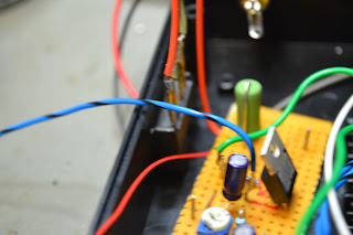
Rectifier board and PWM FET
Rectifier was a little overkill! Still I had two identical, salvaged from a switched mode PSU.

Setting up ready for calibration...
Apply 28.28VDC accross the outputs of the two bridge rectifiers, and with the unit set to 8 Ohms, adjust each pot until the display reads 50.0W. Easy... (Why 28.28V ? 20 VRMS into 8ohms is 50Watts. 20*1.414 = 28.28Vpk... see here for more)

All calibrated and ready for action!
Top line on the display reads left channel, bottom reads right. The three readings are instantaneous power, average and peak.
And last, but by no means least... the code....


Hello, congratulations on the project. What is the maximum power?
ReplyDeleteIt's largely dependent on the power handling of the load resistors. It's calibrated to 50W, but I wouldn't run it for log at that power, especially when set to 4.7ohms.
DeleteHow could it change to run at 100 watts? It's possible?
DeleteYes. Increase the power handling of the resistors to match, change R3 & R8 to ~47K and change the scaling in the software.
DeleteHello! I built the circuit and it really works. Thanks for sharing. I don't have much experience with the software. Can you guide me how to change the scale in the software? Thank you again!
DeleteWhat (watt Hehe!) scale are you looking for ?
DeleteI would like a scale with a maximum of 120 watts at 8 ohms. It's possible? Thank you
ReplyDeleteFirst off , we'll need to change the voltage divider. The A to D can only handle a maximum voltage of 5V. 120W will give us an RMS voltage of 39.984, a peak to peak of 43.81 which will fry our A to D. We need to change R3 and R8 to something greater than 78K to be safe. Use a 68K, and a 10K in series. Next we will need to scale the software. Change lines voltagePk = sensorValue * (35.0 / 1023.0); //Convert the analogue reading to a voltage to voltagePk = sensorValue * (44.0 / 1023.0); //Convert the analogue reading to a voltage. You will need to calibrate the circuit with a 38.983 (call it 31V) RMS sine wave. You can use a DC supply set to 43.8V also (probably easier). Adjust the trim pots to set 120W.
DeleteFriend, thank you very much for clarifying. I will try to make these changes and return with the results.
DeleteHello, could you please tell me from where you've got the values 35 and 44 used to scale the software? thank you.
ReplyDeleteThese are the PEAK (not RMS) voltages we can expect to see for the two impedances selected.
DeleteThank you for your quick reply, my understanding was that those values are related to the power and not to the impedances. I will give it a try for a 200W audio amplifier. I don't know why Google doesn't let me use my Google account and I appear Anonymous. Thank you again, Alex.
ReplyDeleteHallo, Ich ein Problem mit dem Code es kommt die Fehlermeldung sty \303" in programm. Was kann das sein? Ich benutze Arduino 1.8.8
ReplyDeleteVielen für die Unterstützung
Hallo, was kann das sein? Ich bekomme die Fehlermeldung stray \303" in programm. Ich habe Arduino 1.8.8
ReplyDeleteVielen Dank für die Unterstützung
Hallo, Ich habe ein Problem mit dem Code würden Sie bitte helfen.
ReplyDeleteexit status 1
stray '\303' in program
Was kann das sein? Ich benutze Arduino 1.8.8
Vielen Dank