Translate

Showing posts with label Cassette. Show all posts

Friday, 5 August 2022

The C2N'terface

So, we're here, sorting out our micros, and I've hit a problem... 

I'd love to build a Raspberry Pi based 1541 emulator, but Pi's are currently unavailable due to the dreaded chip shortage, and I won't pay "scalper" prices, so that's out. What's needed is to connect my age-old trusty MP3 player to our VIC-20 (or C-64/128 , PET ... anything that wants a C2N plugged in!)

Now the PET, VIC and C64 don't really have an audio in, like a ZX81 or Spectrum. They expect a processed square wave pulse train. 

A bit of an internet search, followed by a good look at the schematic of a C2N, and a plan is hatched. 

Saving is easy ... what's needed is a simple voltage divider, a shade of filtration, and a capacitor to block any potential DC upsetting the record function of my MP3 player.

Playback not so easy ... we need to peak the signal with an op amp, and square it off with some buffers. 

Here's the original C2N diagram:


The signal comes from the record/play head at a very low level, and amplified by the first 3 op-amps, IC1-2, IC1-1, IC2-1. The signal is centered around 2.5V, as there's a voltage divider formed by R18&19. The last op-amp, IC2-2 starts to clip the waveform, as it's run out of headroom. IC3-1 & IC3-2 are inverters (even if they aren't shown as such, look at the waveforms) and square off our signal to +5V square wave.

Recording is the reverse, except the inverters directly drive the record/play head. 

There's motor drive and "sense" which detects the play key being depressed. 

So here's our MP3 player interface... 


Audio comes in at J2, is DC blocked (just in case), and passes through a level control pot RV1. It's given a bunch of amplification by our op-amp, and the output is already pretty much a square wave at this point, but it's followed by either 2 or 3 inverters. The absolute phase of the interface is defined by the jumper, JP1. There's some talk on the internet that this is important. I'm not convinced, but I'm already into an inverter IC, so it may as well be a hex one! The resultant square waves are sent to the computer. A crude level indicator is provided by U1D driving an LED. This should be flickering a bit during loading. A motor drive indicator LED is also provided, driven by another spare inverter! 

Saving is easy, a voltage divider is formed by R8 and R1, and a bit of filtering by C4, the output should be in the region of 640mV pk to pk. This is fed to the line level input of my mp3 recorder via a DC blocking capacitor, C1.

The sense line is held low, so the computer will always think the play key is down. 

A board is duly designed, and sent off for manufacture. 


... and arrives a few weeks later and is populated. There's a snafu on the original layout, which involved a couple of bodge wires. This has been sorted in the latest revision!

Both saving and loading to both a Tascam wav recorder, and to my aging Acer MP3 player work well... there's a tip to setting the volume level to achieve reliable loading. The LED should be *just* glowing when the carrier is present. Once it's set it can be left alone.

Using the audiotap programme for Windows (here) it's easy to convert downloaded .prg or .tap files to a .wav file for playback. MP3 also worked flawlessly at 256 kbps. I didn't try less. 
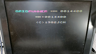
A few rounds of Llamasoft's Gridrunner were enjoyed :)


Sunday, 30 May 2021

Sony TC-161SD repairs.

Colin phoned

"My mate Susie's got a Sony Amplifier only working on one channel, care to take a look?"

Yeah... why not.

It's a Sony TA-1055. 

It was the world's easiest fix. A noisy tape monitor switch, which, after a few operations put itself right.

Susie also has a Sony TC-161 SD cassette deck. 


It's a top loading deck dating from 1972. 

This one doesn't play or record... Let's have a look...

We need to get in from the bottom. There are 6 screws, some recessed, in the bottom panel. This enables us to remove (after a bit of wiggling) the plastic bottom, and wooden case in one go.


This machine is lacking take up, but rewind and fast-forward work after a fashion, although at a somewhat leisurely pace! The fault's are bound to be mechanical.


The machine is able to detect movement of the tape using a small hall sensor, located on the pulley which is fed from the reels, and eventually leads off to the tape counter. If the hall detector stops seeing tape movement, it engages a solenoid, which stops the mechanism. This is how the autostop mechanism works.


Whilst the belts aren't in great condition, they are working, but are replaced anyway. The small idlers (there are three, one take up, one rewind and one fast-forward) are cleaned up with rubber rejuvenator, but are in remarkable condition. 

Now we have great rewind and fast-forward, but still no take up, which the autostop mechanism detects and stops the deck before our cassette is a mangled mess. The take up idler is not engaging. 

Sadly, it's rather buried under one of the capstans (This is a two capstan deck). You can just see it beneath the large grey capstan flywheel. 


Some disassembly is required...  


Removal of the capstan and flywheel gives us good access. 

The idler swivels into position, and tension is applied by a spring to engage it between the capstan and the take up clutch.. except it can't as the joint in the arm has seized solid. A little application of localised hot air from the SMD hot air soldering station frees it up, and when it's cool, a spot of oil is added. It now moves freely.


With everything reassembled, we now have all functions working... 


... except listening to the output, we've got very weak audio, and occasionally oscillation. Putting a blank tape in the machine and working the record button several times clears the fault. It's a tarnished record/play switch. A quick squirt of servisol helps. OK, we've now got playback but no recording. I can *just* hear audio, but it's very faint. Just as I'm beginning to suspect the record-play switch again, I switch Dolby off. Up comes record audio. Switch it back on and it's a bit intermittent. Another quick squirt of servisol to the dolby switch and all is well. I've also done the limiter, and tape selector switches as well as the record volume controls, just to make sure.


Saturday, 27 June 2020

Yamaha KX-580 fail...

It's the last of the famous George's kit to look at ...


It's a mint condition KX-580 with a nasty noise on the left hand channel.

When I say mint, I mean mint... it looks like it's never seen a cassette in it's life.


Sadly I rapidly trace the fault ... it looks like an open circuit head ...


... and sure enough it is ...


Game over. It's a special low inductance GX-37 head , and utterly unobtainium. I hate being beaten, but sometimes that's just the way it is....

Friday, 12 July 2019

Sharp RG-3915 In-car radio cassette repairs and restoration.

I bought this on eBay..


"Why?"  I hear you ask...


Because I've been spurred on by the warm summer evenings to finish off the green thing lurking in the garage... and it needs some suitable retro sounds. (Sorry if you're still waiting for the final Sony 9-306 YouTube video)

The RG-9305 is an auto-reverse radio cassette, released in 1983 (OK, it's a bit newer than my car, but hey..) It produced a trouser flapping 8 watts per channel (although some have appeared to have escaped.. read on!)

The seller assured me it was "working when removed" ... which I can only assume was sometime in 1985 ;) Thankfully I use the usual eBay translator for such. "Working when removed" means been sat in a damp shed for 30 years+ and the seller can't be ars bothered to test it. (For more eBay description translations check this out)

... and sure enough I'm not disappointed... the cassette deck doesn't work, and the radio is weak and distorted. The radio comes on for a few moments, then the volume fades away rapidly.

Let's tackle the tape first.

Take off the knobs and the securing nuts and remove the faceplate(s) ...


Remove the two screws holding the front panel. It should just pull away.. The remove the four screws to remove the top panel (two on the top in the label, and two on the front). Remove the top panel by gently prising it up with a small screwdriver.


The cassette mechanism is held in place with two screws on the front panel. Disconnect the motor/control plug adjacent to the motor, and the head wiring plug next to the volume pot.

Pop the eject button off (bottom left), and, although it's tight, you should now be able to extract the mechanism complete...

Excellent. Turn it over....


.. and remove the two screws holding down the capstan flywheel retaining plate.

Remove the two offending belts, find suitable replacements in the belt box, and replace them...


Yeah, they're shot ... ;)


Here's an interesting manufacturing technique... real printed components...

It looks like R120, R62 et al are just printed blobs of some carbon type of material, not dissimilar to the "thick film" type of construction used in some TV's back in the day, but those were usually printed on ceramic, not ordinary PCB material. Even the tracks on this side of the board don't appear to be copper, but some form of conductive paint or ink. What if there's been some flexing and vibration going on and there's a microscopic track break? This fills me with dread ... let's see what happens.

On test and the output is low and distorted. There's about 3VDC appearing on the speaker outputs. Not good.

Reverse engineering the circuit shows the output amplifier is coupled to the speakers by two capacitors. They're leaking.


As there's a few others right close to the amplifier, I change the lot...


Ok... things are better, but there's still precious little output, and what there is, is still distorted and thin sounding. Tracing the circuit back from the amplifier, I get to a uPC1228 op amp. It's a dual amp, but in a single in line (SIL) package, and made from unobtainium.. The DC conditions around the amp are odd... There's a DC off-set on the input, which is building over the first second or so the unit is switched on. The audio is coupled in via two capacitors, and loaded by two of those printed resistors I mentioned earlier... and they prove to be open circuit.

An educated guess is made, and two 100K resistors are duly lashed up. One between pin 1 and gnd, and the other between 6 and gnd.

Audio is restored :)


The replacement resistors are properly mounted.


Now the case has a chunk missing out of it, across the top where the cassette goes..


I used the remaining corner to bend a piece of tinned copper wire to get the outline shape. This is then flipped over, and warmed up with a soldering iron and melted into the plastic case...

It's rubbed down a bit, and covered with capton tape.


Some car body filler is mixed up, and used to fill against the tape. Once the filler has hardened, the tape's removed and the filler trimmed with a craft knife to the rough shape required.


A little more filler is added...


... and finally sanded down to get the final shape.


A trip to a local paint supplier to get a matching colour ... a quick browse through the racks shows this Pastikote radiator paint looks a damn good match ...


The front panel is carefully masked off...


... and painted. I'm rather pleased with the colour match and end result...


The faceplate gets a coat too to get rid of a few scuff marks, and the unit mounted in an under-dash box ready for fitting


and I've got one of these bluetooth FM transmitter devices so I can play music from my phone! (£7.22 on eBay!)


Another saved from landfill :)

Wednesday, 5 December 2018

Philips Digital Compact Cassette recorder repair DCC 951

I missed out on the whole DCC thing. I was a big fan of minidisc...

Anyway, this found it's way into my possession....


It's a DCC 951, dating from 1994. It doesn't work. It's totally dead.


Off with the lid ...


Poking around with a multimeter proves there's AC on the output of the transformer. Time to examine those "wickman" fuses on the rear PCB...


Which involves removal of the back panel, which is easy enough... a few torx screws, and bending these little tabs out of the way ...


One on each side...


.. and lifting the panel off. The mounting screws can now be removed from the PCB, and it can be hinged up without disconnecting anything...


Sadly the wickman fuses are all intact ... but the regulators on the heatsink are horribly dry-jointed, and a quick solder up on these, and the mains input socket and switch (which are also looking poor) , solves the problem!


Great front loading mech... really smooth!

A conventional analogue tape can be used (analogue only, sadly), and goes in with the exposed side forward. Sadly I don't posses a DCC casette to see what the digital bit's like.

I clean up the tape path, and change the loading belt (it was OK, but I had a new one to hand!)
DON'T DEMAGNETISE THE HEADS!


Here's a few other shots...


... now to find a cassette ... anyone?