So, we're here, sorting out our micros, and I've hit a problem...
I'd love to build a Raspberry Pi based 1541 emulator, but Pi's are currently unavailable due to the dreaded chip shortage, and I won't pay "scalper" prices, so that's out. What's needed is to connect my age-old trusty MP3 player to our VIC-20 (or C-64/128 , PET ... anything that wants a C2N plugged in!)
Now the PET, VIC and C64 don't really have an audio in, like a ZX81 or Spectrum. They expect a processed square wave pulse train.
A bit of an internet search, followed by a good look at the schematic of a C2N, and a plan is hatched.
Saving is easy ... what's needed is a simple voltage divider, a shade of filtration, and a capacitor to block any potential DC upsetting the record function of my MP3 player.
Playback not so easy ... we need to peak the signal with an op amp, and square it off with some buffers.
Here's the original C2N diagram:
The signal comes from the record/play head at a very low level, and amplified by the first 3 op-amps, IC1-2, IC1-1, IC2-1. The signal is centered around 2.5V, as there's a voltage divider formed by R18&19. The last op-amp, IC2-2 starts to clip the waveform, as it's run out of headroom. IC3-1 & IC3-2 are inverters (even if they aren't shown as such, look at the waveforms) and square off our signal to +5V square wave.
Recording is the reverse, except the inverters directly drive the record/play head.
There's motor drive and "sense" which detects the play key being depressed.
So here's our MP3 player interface...
Audio comes in at J2, is DC blocked (just in case), and passes through a level control pot RV1. It's given a bunch of amplification by our op-amp, and the output is already pretty much a square wave at this point, but it's followed by either 2 or 3 inverters. The absolute phase of the interface is defined by the jumper, JP1. There's some talk on the internet that this is important. I'm not convinced, but I'm already into an inverter IC, so it may as well be a hex one! The resultant square waves are sent to the computer. A crude level indicator is provided by U1D driving an LED. This should be flickering a bit during loading. A motor drive indicator LED is also provided, driven by another spare inverter!
Saving is easy, a voltage divider is formed by R8 and R1, and a bit of filtering by C4, the output should be in the region of 640mV pk to pk. This is fed to the line level input of my mp3 recorder via a DC blocking capacitor, C1.
The sense line is held low, so the computer will always think the play key is down.
A board is duly designed, and sent off for manufacture.
... and arrives a few weeks later and is populated. There's a snafu on the original layout, which involved a couple of bodge wires. This has been sorted in the latest revision!
Both saving and loading to both a Tascam wav recorder, and to my aging Acer MP3 player work well... there's a tip to setting the volume level to achieve reliable loading. The LED should be *just* glowing when the carrier is present. Once it's set it can be left alone.
Using the audiotap programme for Windows (here) it's easy to convert downloaded .prg or .tap files to a .wav file for playback. MP3 also worked flawlessly at 256 kbps. I didn't try less.
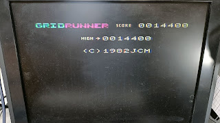
A few rounds of Llamasoft's Gridrunner were enjoyed :)


