Now, being a gadget lover that I am, I decided to upgrade the rather old dashcam in my car to something a little more "HD". After doing a bit of research, and seeing the footage of a colleagues camera, I decided to get a Mobius 1080P Actioncam, purchased from a reputable source (beware the fakes). Good choice. Small unit, great pictures, sound is OK... except....
... it ruined my radio reception.
Now I have a newish car, and it's fitted with a DAB radio. After fitting the camera to my windscreen, I noticed DAB reception of my favourite station, Planet Rock, became patchy. Disconnecting the camera solved the issue.... hmmmm ... RFI ... Radio Frequency Interference.
So what was going on? I broke out my ancient spectrum analyser, and, equipped with a simple whip antenna, took some measurements....
Here's the DAB reception, centred on 220MHz, with the Mobius disconnected. The two humps are the two DAB Mux's (multiplexes) I can receive at home...
... and here's the same shot with the camera connected... yuck. I suspect the big peak to the right of the mux is effecting the AGC of the radio, and there's a lot of hash underneath it too, upsetting the signal to noise ratio... boo!
I tried a simple method of preventing RFI radiating from the cable of the device. I wrapped as many turns of the USB power lead round a random (ex-computer power supply) ferrite ring.
Brilliant....
... and after some field tests, reception restored!
Many, many moons ago I needed something to measure audio power in a hurry. So I lashed up a quick and dirty audio power meter.
It was nasty....
... very nasty, but did the job at the time.
It was simply a switchable 4 or 8 ohm load (actually 4.7 or 8 ohms) which was rectified, and used to drive two meters, each measuring full scale at 10 watts. The fan was driven from rectified audio. Most unpleasant.
Anyway, the load was good, as was the fan, but I needed some sort of better instrument, so a plan was dreamt up. Measure the peak voltage across the load, do a bit of maths and get the results displayed on a 1602 display, driven by an arduino. Great ....
So audio comes into the load (R1 & R2), and is rectified by a bridge. There's a small bit of smoothing on the output, so we can get a steady-ish DC. This is divided by a voltage divider, R3 and R4 and the resultant is fed to the arduino's A-D converter. Couple of things to note here, the load is switched, either 8.0 Ohms, or 4.7 Ohms, by S1. This also lets the arduino know which load is selected. S2 is a "BTL safety switch". It completely isolates the left and right channel. It also stops the arduino reading the right channel. If you're testing a BTL(bridge tied load) amp, or any type of amp which may not take kindly to commoning up of the negative poles of the speaker, best click this across. It also grounds the second analogue input to prevent spurious readings. A PWM signal is output from D6, and is used to drive a FET to run a fan. I chose a stupidly large FET here, you can pick something more sensible. I just happen to have a bucket of them.
This will only give accurate results when feeding in a sine wave.
That's it really....
Dummy load salvaged from the old unit...
Front panel coming together.
... sizing it all up....
... starting the wiring...
Looking good until I noticed that I'd mistakenly picked up a 16x1 display instead of a 16x2!... and the 16x2 requires a slightly smaller opening. Drat! ... some hot melt later will have to do (and it was all going so well ...)
Rectifier board and PWM FET
Rectifier was a little overkill! Still I had two identical, salvaged from a switched mode PSU.
Setting up ready for calibration...
Apply 28.28VDC accross the outputs of the two bridge rectifiers, and with the unit set to 8 Ohms, adjust each pot until the display reads 50.0W. Easy... (Why 28.28V ? 20 VRMS into 8ohms is 50Watts. 20*1.414 = 28.28Vpk... see here for more)
All calibrated and ready for action!
Top line on the display reads left channel, bottom reads right. The three readings are instantaneous power, average and peak.
Back in about 1981-82, I bought one of these sets from a jumble sale for 50p. I lugged it all the way home, stopping many times along the way (I was only 10 at the time). It didn't work. My mum kindly took it into the local TV shop (Seamen's Television in Carshalton) and they fixed it for me. It's a larger 17" TV, using a hybrid chassis of valves, transistors and 2 IC's, 625 line single standard, black and white.
It's more "trans-luggable" really, you can see that woman in the ad straining, it's got some weight!
The fun continued until about 1985 when the tube failed, curtailing the fun. It was binned.
I'd kept a casual eye on eBay for one for the last few years, and then in late 2014 one surfaced.
I collected it from the south coast and returned home with it.
Cosmetically in good nick, although the tuner was seized solid.
A few repairs have been carried out in the past...
.. but it looks OK.
Callins electrolytics are most likely to be faulty...
TAA700 sync separator and video pre-amplifier chip.
These sets had a reputation for poor caps in the line stage, they've been changed in the past..
Mazda CME1713/ A144-120 tube. Flaky aqua-dag, but that shouldn't effect performance.
So, the mains filter capacitor was snipped out, and some mains applied via the variac.... and, the smell of burning dust and hot valves awaking from their slumber filled the workshop... a few moments later , a picture appeared! Tube looked to have plenty of life left. I went to the kitchen to get a cuppa, and on return was greeted with a VERY hot dropper resistor, and a line output valve glowing cherry red :(
Probably one of those rotten caps stopping the oscillator I thought ... I thought wrong. After an hour or so of testing, I pulled out the line transformer, and performed a ring test ...
No doubt it had developed shorted turns. The TV restorer's worst nightmare.
I asked everywhere to see if anyone had a replacement transformer. I had a few leads, but nothing was forthcoming....
It's probably the EHT overwind, I thought, so the plan was to remove the overwind and ring test that to see if that was at fault. I had some other unknown line output transformers I could take the overwind from.
Unfortunately nothing would shift the glue used to hold the winding to the ferrite core. Disaster struck, it broke up ...
I reassembled the set and stored it in the attic, until a suitable transformer could be obtained.
Time passed, a lot of time......
and then, several weeks ago, a wonderful gentleman emailed me from one of the forums, who had seen my request for a transformer. He suggested a Philips 210/300 chassis transformer may be a suitable substitute. He had a Konig replacement, a ZTR371, which had the benefit of having a solid state EHT rectifier built in. It duly arrived in the post...
The set was removed from storage, and prepared for the transplant!
Both the Philips and Pye circuits were examined... there were differences. Mainly in how the line linearity is handled.
I initially decided to modify the Pye circuit, to accommodate the Philips positioning of the line linearity coil... stood well back and slowly increased the mains on the variac. Almost no width, but there's something....
I then changed the circuit back, and changed the wiring on the transformer to suit the Pye line linearity cicruit... results were much improved, although "boost" HT was woefully inadequate at about 320V, 850V would be better...
The reason for the lack of boost HT was quickly spotted.... another wiring change...
It's all a bit of a lash up of bits of wire and croc clips, but it IS working.
During this time I noticed there was now a precious lack of "snow" on the screen. I decided to stop here, and evict those awful Callins electrolytics, and anything else which looked suspect.
... and un-seize the tuner.
... lots of surface rust on the tuning spindles, which is cleaned off using a little WD40 on a cotton wool bud.
The cam-gear on the other side is also stiff, but eases with a little WD40.
After it's all moving again, I cleaned off the WD40, just in case it attacks the plastic nuts on the spindles. A good coating of spray grease should keep everything lubricated.
So, the tuner is reassembled and fitted back to the set. I can now tune in the set, and can *just* see a picture, but it's totally lacking in contrast. Time to evict all those nasty electrolytics. Many are either physically leaking, cracked or electrically leaking or low in value. Sadly, this doesn't fix the issue. On a brighter note, the height and width are improving, probably due to the valves waking up after a long slumber! I add a 100pF capacitor across the line harmonic tuning cap, which improves the amount of adjustment available on the width control.
I mount the line output transformer permanently, and tidy up the wiring.
So, back to the lack of contrast. The video is demodulated by the TAA700 IC. Expect for in this case, there was precious little video coming from the IC. I find a few resistors outside of spec, but changing these makes no difference. I fit a new IC. No change.
Scoping up some of the waveforms around the IC shows it not quite getting the right information back from the line output stage to correctly operate. Unsuprising considering the wrong line output transformer is fitted. It's probably stuck in blanking...
I turn my attention to the line stage, and R 92 in particular.
I connect a 1 megohm pot and a 100K resistor in series, and connect it across R92, in an attempt to increase the drive to the IC.
Tune for maximum smoke. Only it doesn't work, as I get the required pulses at the IC , the picture gets worse! ... So I re-wire the pot so as to decrease the pulses to the IC!
Bingo! Pots of contrast. I disconnect the pot and take a measurement of the value. It's near enough to 1 megohm, so R92 is replaced with a fixed resistor.
Now just to centre up the picture and soak-test it...
... if only...
You might glaze over at this bit ....
After being on for about half an hour, the picture faded out rapidly. I cut the power quickly. Is this the return of the fault that had killed the original transformer??? The new transformer is running a little hot. Perhaps a bit hotter than I'd like. The boost capacitor, and the first anode decoupling capacitor have both been replaced in the past, it was probably in the 80's at the latest, so I order some up. Replacing these makes no difference, and half an hour later the set cuts out abruptly again, as the line output stage shuts down. I wait for a few minutes, and scope up the line drive signal to the PL504 output valve. It remains strong, even in the fault condition, so something is loading down the line output stage. I change the PL504 and PY88 boost rectifier, and I'm rewarded by more width, so I remove the 100pF cap I'd previously fitted to improve the width. Sadly after a few mins, the line stage once again shuts down. I move the width stabilisation feedback from the direct tap on the transformer, to the capacitively coupled tap. This improves the range of the width control further, but doesn't sort the fault... phut! The set goes off.... I give any remaining suspect components in the line output stage a liberal squirting of freezer (on the cheap). Sadly it appears the line output transformer can't cut the mustard. It's failing when warm. I'm about to give up. It has taken hours and hours of work to get this far, and I hate to be beaten, but enough is enough.
I made some tea, and studied the circuit diagram again. Nothing is really forthcoming. I decide to cut apart the original Pye transformer to see if I can learn anything from the windings. I make some simple resistance measurements and compare them to the Philips transformer. The winding I'm supplying the HT to is a lot lower resistance than the Pye transformer. It should therefore be drawing more current. I scope up the current flowing into the transformer using a totally inappropriate hall-effect amp-clamp, which appears to tell me there's 2A flowing into the lopt. I suspect there's a lot less than this in reality. I can see there's an unused tap on the primary of the Philips transformer, so I hook up the HT feed to this tap. Now my (lying) current probe tells me there's an amp flowing into the transformer, well that's a change in the right direction. The picture comes up, and stabilises, the width is still good, and stays there .... for hours .... Success at last!
So for future reference, here's a quick sketch on how to fit a Philips 300 transformer to a Pye 169!
Some of the guilty & redundant parties...
Obligatory arty valve shots (seem to be getting the hang of this Nikon camera now!)
...and here's a video of the thing in action (maybe not so good with the new camera!)...

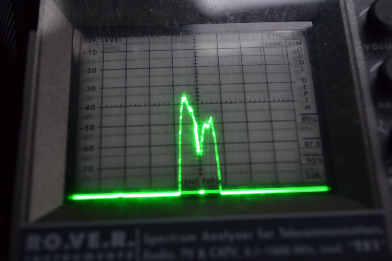 Here's the DAB reception, centred on 220MHz, with the Mobius disconnected. The two humps are the two DAB Mux's (multiplexes) I can receive at home...
 I tried a simple method of preventing RFI radiating from the cable of the device. I wrapped as many turns of the USB power lead round a random (ex-computer power supply) ferrite ring.
 Brilliant....


